Description of the AXC F 1050
107709_en_00 PHOENIX CONTACT 33 / 140
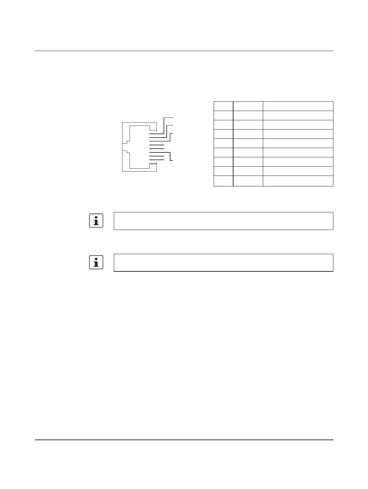
3.10.1 Ethernet
The controller is equipped with two Ethernet interfaces (X1/X2).
The Ethernet network is connected via RJ45 sockets.
The contact assignment of the interface is as follows:
Figure 3-12 Ethernet interface and pin assignment
3.10.2 Service interface (Micro-USB type B)
Pin Signal Meaning
1 T+ Transmit data +
2 T- Transmit data -
3 R+ Receive data +
4– –
5– –
6 R- Receive data -
7– –
8– –
The Ethernet interfaces are able to switch over the transmitter and receiver automatically
(auto crossover).
The service interface (Micro-USB type B) is currently without function.
RJ45
Pin 1
Pin 2
Pin 3
Pin 4
Pin 5
Pin 6
Pin 7
Pin 8
 Loading...


