Hunter-Pro Series & Captain 8 Installation Guide
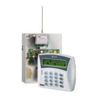
Diagram 20. LCD keypad PCB and wiring
3.8 TMPR1/TMPR2
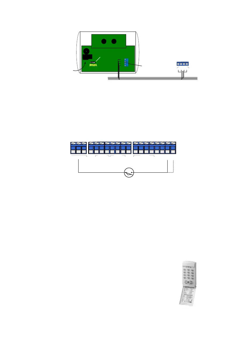
Connect tamper switches between the TMPR1/TMPR2 terminals and GND (-); see the next
diagram. Note that the control panel case’s tamper switch is connected to TMPR1 terminal.
TMPR2 input can be programmed to serve as additional zone (#9); see next sub-section.
To use the TMPR inputs with EOL loops, refer to section 6.8.1, on page 65.
Diagram 21. Tamper switches wiring
3.8.1 TMPR2 input as additional zone input
This feature can only be used if no expander is connected to the panel. It is set in the
“General Parameters - First Screen” menu ; see page 65.
3.8.2 LED Keypad: RXN-9
RXN-9 is a 9 zone LED keypad. It can control any number of zones, but display only zones
1-9. When using partitions, if more then 9 zones are in use, the keypad will not display
zones 10 and above, but will only serve to arm and disarm them.
The RXN-9 is connected to the BUS like any keypad and can be supervised too;
To set the keypad ID:
1. Remove the keypad’s backplate.
2. Place the JP1 jumper on the left 2 pins.
3. Enter the new ID, 1-8; the key should illuminate briefly.
4. Return the jumper to the 2 right pins;
5. Replace the backplate.
RJ-11 socket
Control panel
4 ( I N )
3(OUT)
2 ( + )
1 ( - )
JP1
PROGRAMMING
BUS
1
KEYPAD
1
2
3
4
-
+
IN
OUT
ID jumper
Removable
terminal block
Tamper switch
Control Panel
TMPR
2
TMPR
1
ON
/
OFF
ALRM
Z
8
-
+
KEY
-
Int
C
S
moke
RELAY
SIRENS
KEYPAD
Ext
N
.
O
-
-
+
IN
OUT
1
2
3
4
N
.
C

 Loading...