Hunter-Pro Series & Captain 8 Installation Guide
Diagram 22. RXN-9 PCB connection diagram
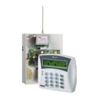
3.9 Telephone LINE/SET
LINE: connect a telephone line directly to the LINE terminals. This will give the control
panel priority when initiating a phone call.
SET: connect telephone sets, answering machine, etc., to the SET terminals. When the
control panel initiates a phone call (or receives one), these terminals are temporarily
disconnected.
Diagram 23. Telephone LINE/SET wiring
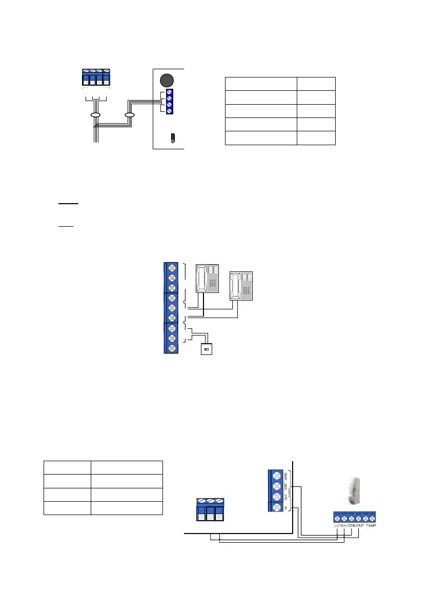
3.10 AUDIO
3.10.1 MIC-200 microphone
1. Connect the MIC-200 to the AUDIO terminals as described in the next table and diagram.
2. In the "Output configuration" menu, set the AUDIO output polarity to ‘+’ (see section
6.10.4, on page 69).
Note that the MIC-200 is supplied without wires.
Control Panel
RXN-9
JP1
OUT IN
1
BUS
KEYPAD
-
+
IN
OUT
1
2
3
4
1 2 3 4
- +
Telephone line
Telephone/Fax
C
O
N
T
I
N
O
U
T
L
I
N
S
E
T
A
U
D
I
O
A
G
N
D
E
G
N
D
E
MIC-200
Control panel
Zones’ voltage

 Loading...