Hunter-Pro Series & Captain 8 Installation Guide
2. Set the "Audio control" (or any other) output type to trigger the outputs.
3. Set each output's partition/s in the “Part. For Out” screen. You must set a different
partition for each output, i.e., the same partition cannot trigger both messages.
4. Set the outputs' polarity ("P") to (-).
3.10.3 SMS-100
To connect the SMS-100 module to the control panel, see the next diagram and table.
Diagram 27. SMS-100 wiring diagram
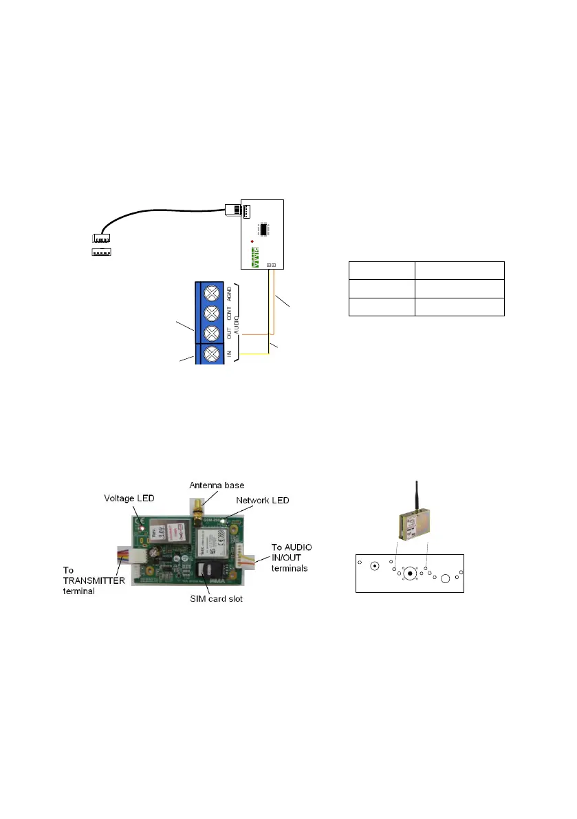
3.10.4 GSM-200 cellular communicator
The GSM-200 cellular module can serve both as a main or backup communication channel.
It connects integrally at the control panel case. See the figure in section , on page .
See mounting guidelines in section 8.6, on page 83.
Figure 3. The GSM-200 PCB and mounting holes
SMS-100
Yellow
Control panel
Orange
TRANSMITTER
JP
1
P2
P1
A out
A in
JP1
AUDIO OUT
AUDIO IN
GSM-200
Control panel case’s top side

 Loading...