Hunter-Pro Series & Captain 8 Installation Guide
5. In the "Zone responses" menu, set the zone type/s to trigger the audio device when
violated, by setting parameter "M" to “+”; see section 6.4.2, on page 50.
6. Set the control panel to play the voice massage instead of the alarm sound, when it calls
the end user: in the “Communication Options” menu, set “V – Voice unit” to “+”; see
section 6.5.4, on page 54.
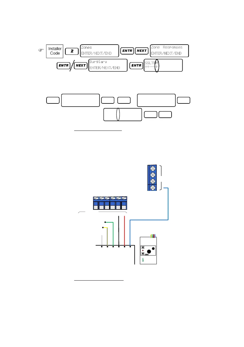
3.10.2.3 Two message wiring
1. Connect the Green wire (M1) to the first output (including in the zone expanders).
2. Connect the Yellow wire (M2) to another output.
3. Connect the +/- wires to the control panel's zones’ voltage.
4. Connect the Blue wire to the control panel's AUDIO IN terminal.
Diagram 26. VU-20U two message wiring
3.10.2.4 Two message setting
To use the VU-20U for two messages, the panel must be set with two partitions: each partition
will trigger a different message; see section 6.4.5, on page 51 for instructions.
To set the messages:
1. In the "Output configuration" menu, select the two outputs to which the VU-20U will be
connected to and triggered by; see the programming diagram on section 3.12.3.
3
ENTR ENTRNEXT
X3
Communication
ENTER/NEXT/END
Commun. Options
ENTER/NEXT/END
PTLLTAVDRPOSD
+---+-+++-+--
ENTR END
AUDIO IN
Control panel
Blue
Red
Black
Green
Yellow
Audio
VU-20U
White
M1
M2
CONT
+12V
GND
M1: to the first output
M2: to the second output

 Loading...