Hunter-Pro Series & Captain 8 Installation Guide
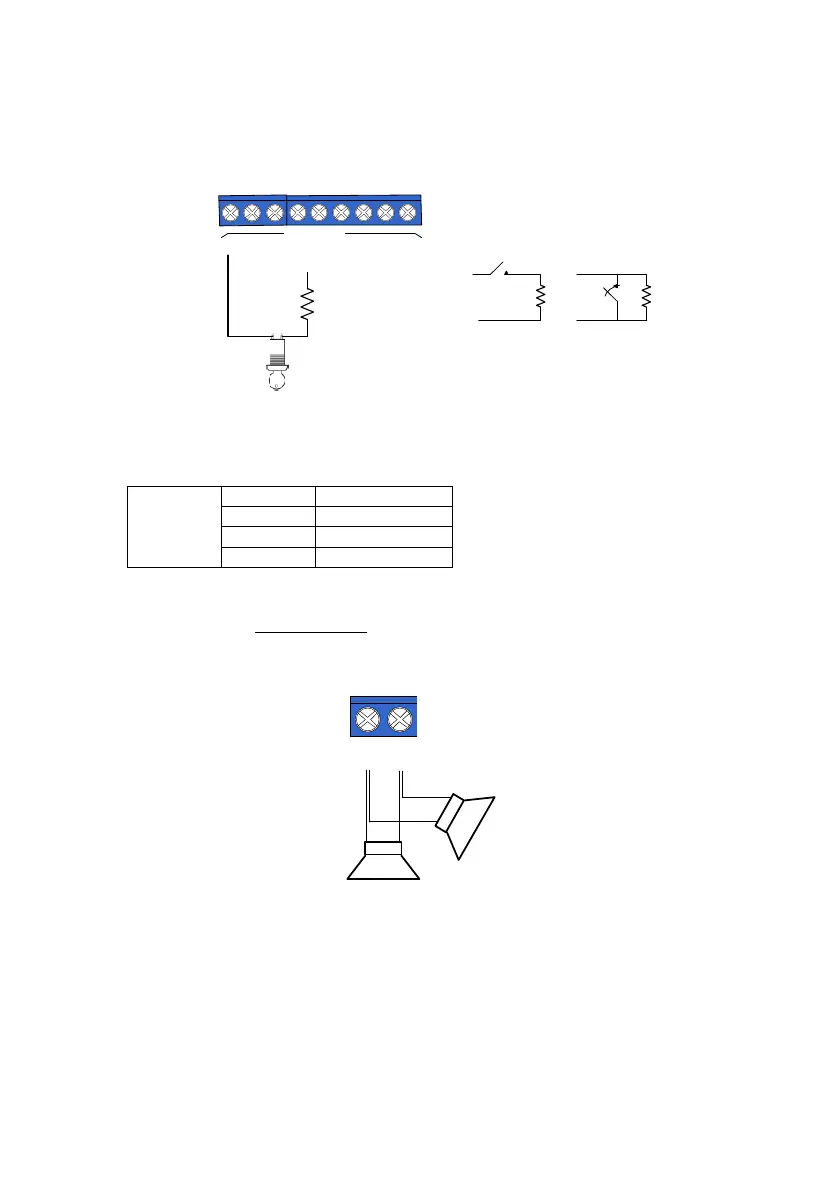
4.3.2 Key zones and key fobs
See section 3.3, on page 23 for details.
Diagram 35. Key wiring
4.3.3 JP3 jumper
The JP3 jumper is set according to the EOL resistor loops; see the next table.
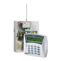
4.3.4 Sirens wiring
4.3.4.1 Speaker/Horn
Connect the sirens between the SRN (-) and (+) terminals, as seen in the next diagram.
Diagram 36. Horn (speaker siren)
4.3.5 Keypad wiring and ID
See section 3.7, starting page 27.
4.3.6 Telephone LINE/SET wiring
1. Connect the telephone line to the LINE terminals.
2. Connect telephone set/fax machine/answering machine to the SET terminals.
GND
N.O.
N.C.
R=10K
Control panel
RR
Ω
Key switch
(-)
KEY
Z O N E S
-
Z
1
Z
2
Z
3
Z
4
Z
5
Z
6
Z
7
Z
8
R