Hunter-Pro Series & Captain 8 Installation Guide
2.2 The control panel’s circuit
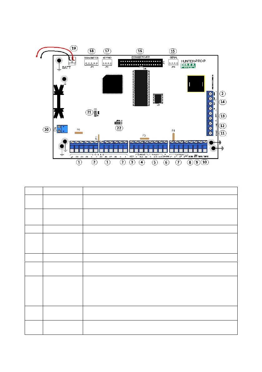
Diagram 1. The Hunter-Pro Series PCB
2.2.1 Terminals, connectors, jumpers & fuses
Description/Connected accessories
8 dry contact detector inputs. Loops can have one or two EOL (End
of line) resistor supervision.
“+”: 12VDC power supply for detectors
“-”/AGND: Common
Input for momentary or ON/OFF key switches and remote controls
Terminals for connecting external and internal Sirens/horns. The
terminals are protected by automatic thermal fuses, F2, F3. See
more details in section 6.10.5, on page 69.
Output for triggering gates, spotlights, etc.
Fire, Smoke & Anti-Mask detectors’ reset output. To manually reset
a detector, press [*] for 2 seconds
Input/output and power supply for keypads & expanders (BUS).
The terminals are:
'+'/'-': 13.8 VDC; F4 thermal fuse protects the terminals
IN/OUT: Data
Transistor output. By default, the output is switched to (-) when an
alarm is set off.
Transistor output. By default, the output is switched to (-) when the
system is armed.

 Loading...