Hunter-Pro Series & Captain 8 Installation Guide
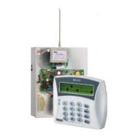
Diagram 18. The Relay terminals
3.7 Keypad (BUS terminals)
The KEYPAD terminals are used for connecting the 4 BUS wires. Zone expanders, keypads and
other peripherals interface the control panel over the BUS braid.
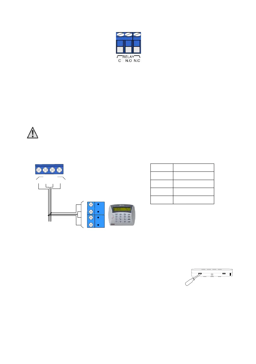
The KEYPAD/BUS terminals are (-), (+), (IN) & (OUT). To make connection easy, these
terminals/wires are numbered 1-4, both in the control panel and in the expanders, so #1
terminals on both ends are connected together, and so the other wires.
Up to 8 keypads can be connected to the Hunter-Pro system ,supervised or not.
The BUS's "+" wire must be separated from any other "+" wire
3.7.1 RXN-400/410 LCD Keypads
Diagram 19. LCD keypad wiring
3.7.2 Setting the keypad’s ID
The keypad's ID is set using a jumper on the PCB. To set the ID:
1. Open the keypad’s back cover:
a) Unfasten the screw at the bottom of the keypad.
b) Insert a flat screwdriver into the two holes to the sides of the
screw and gently remove the cover; see the next figure.
2. Short JP1’s pins 1 & 2; the message onscreen should say: “Enter new ID: X”.
3. Enter the new ID number - 1-8;
4. Short JP1’s pins 2 & 3;
5. Repeat the process with any other keypad. Note, that each addressable keypad must
have a unique ID and that the IDs must be consecutive and in ascending order.
6. If keypad supervision is not required, the keypad's IDs should be left zero.
KEYPAD
1
2
3
4
-
+
IN
OUT
1
2
3
4
(
-
)
(+)
(
OUT)
(
IN
)
Keypad
Control panel
BUS

 Loading...