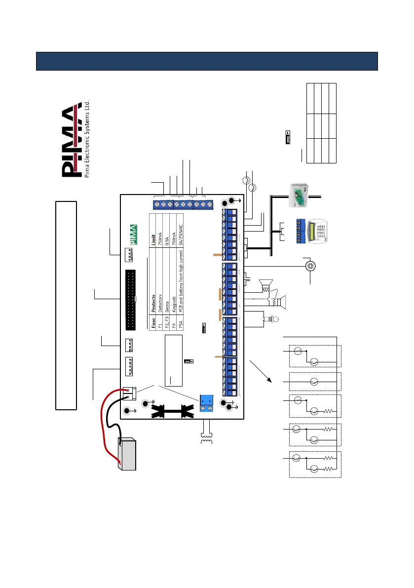
3. Connecting and Wiring
Diagram 3. Hunter-Pro wiring diagram
1KΩ
To
(+)
Red (+)
Black (-)
Rechargeable
Lead-Acid battery
EXPANSION CARD
SERIAL
KEYPAD
TRANSMITTER
JP
1
JP
2
JP
4
F
3
F1
JP
6
F
4
F
2
JP3
HUNTER
-
PRO
P
JP
11
1
TMPR
2
TMPR
1
ON
/
OFF
ALRM
Z
1
Z
2
Z
3
Z
4
-
+
Z
7
Z
8
-
+
KEY
-
Int
C
Z O N E S
S
moke
RELAY
SIRENS
KEYPAD
Ext
N
.
O
-
-
+
IN
OUT
1
2
3
4
N
.
C
Z
5
Z
6
Current limiting thermal fuses
Warning: High voltage!
Disconnect AC power and telephone line prior to servicing
TRU-100/TRV-100 Long Distance Radio,
GSM-200 Cellular Module,
SMS-100 Module Technician
keypad
OUT-1000,
EXP-PRO UNIV
Local expanders
VVR, net4pro,
Home Automation systems
Phone line
MIC-200, VU-20U
(The two modules cannot
be used together!)
MIC-200, VU-20U,
SMS-100 GSM-200 Voice
Answering machine,
fax, telephone sets
2
Transistor outputs
22 JUL 11 22:40
--_----FB__--A-_
4 (IN)
3 (OUT)
2 (+)
1 (-)
BUS
Optional N
.
O
.
or N
.
C
.
serial
&
parallel EOL resistor loops
JP11: EOL resistor loops
TMPR1/2
TMPR2 can serve
as a zone input
(-)
Relay
To zone
input
Fire/Smoke
Detector
Z
1
Z
2
Z
3
Z
4
Z
5
(
-
)
N
.
O
./
N
.
C
.
,
2
EOL
Resistors
N
.
O
.
,
1
EOL
Resistor
N
.
C
.
,
1
EOL
Resistors
N
.
O
.
N
.
C
.
Key
Sirens
To Expanders
& Keypads
1-2
2-3
No Pin
A
A
A
A
A
T
T
T
T
T
:
Tamper
A
:
Alarm
Hunter-Pro Series (Ver. P )
R
2
R
1
R
1
R
1
10
Short PinsR2 (KΩ)
10
13
5.1
10
6.8
R1 (KΩ)
AC
14
VAC
BATT

 Loading...