Hunter-Pro Series & Captain 8 Installation Guide
4.2 The PCB
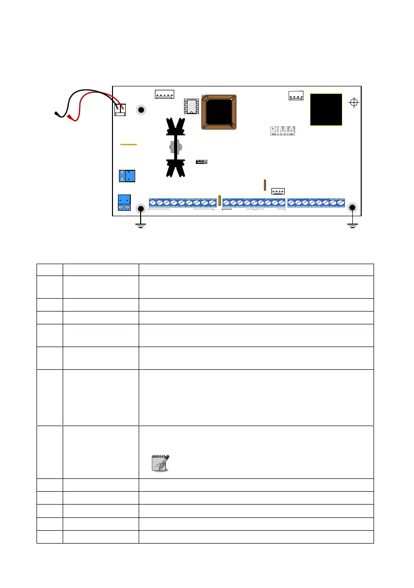
Diagram 33. Captain 8 PCB
4.2.1 Terminals and connectors
Description/connected peripheral
8 dry contact detectors input terminals. The loops can have 1 or
2 EOL (End-Of-Line) resistors.
Fire, smoke & anti-mask detectors terminal
Auxiliary output that can be disconnected or switched to GND,
when an alarm is set off.
Output for connecting up to 2 sirens (with or without internal
driver) in parallel. F1 thermal fuse protects this output.
I/O and voltage terminals for the system's BUS wires. Keypads,
expanders and other peripherals interface the control panel
over the BUS. The terminals are:
-1/+2: 13.8 VDC power supply; thermal fuse F4 protects
the terminals;
3IN/4OUT: Data.
MIC-200 microphone & VU-20U voice module audio
terminals.
Only one of the two modules can be connected
at a time.
Answering machine, fax and telephone sets
RS-232 terminal; is used for connecting the VVR and net4pro
GSM-200 cellular communicator, TRV/TRU-100 radio
-
AC
BATT
U11
TRANSMITTER
PIMA-8
JP3
F3
+V
KEYPAD
10
15
12
SERIAL
11
13
14
Z
1
Z
2
Z
3
Z
4
Z
5
Z
6
Z
O
N
E
S
+
V
S
M
O
K
E
P
G
M
S
R
N
O
U
T
P
U
T
S
-
1
K
E
Y
P
A
D
O
U
T
L
I
N
E
T
E
L
E
P
H
O
N
E
S
E
T
-
A
U
D
I
O
I
N
F
2
Z
7
Z
8
2
3
4
+
I
N
O
U
T
-
EGND
-
+
1 2 3 4 6 7 8 22 5 9
F1
P/N 3610105 Rev. C

 Loading...