Hunter-Pro Series & Captain 8 Installation Guide
3.1 Connecting zones
The overall length of the BUS wires cannot exceed 500 meters. If a longer
distance is required, refer to section 3.2.1, on page 15.
The BUS implements PIMA proprietary protocol.
IMPORTANT! Disconnect all power supply prior to installation!
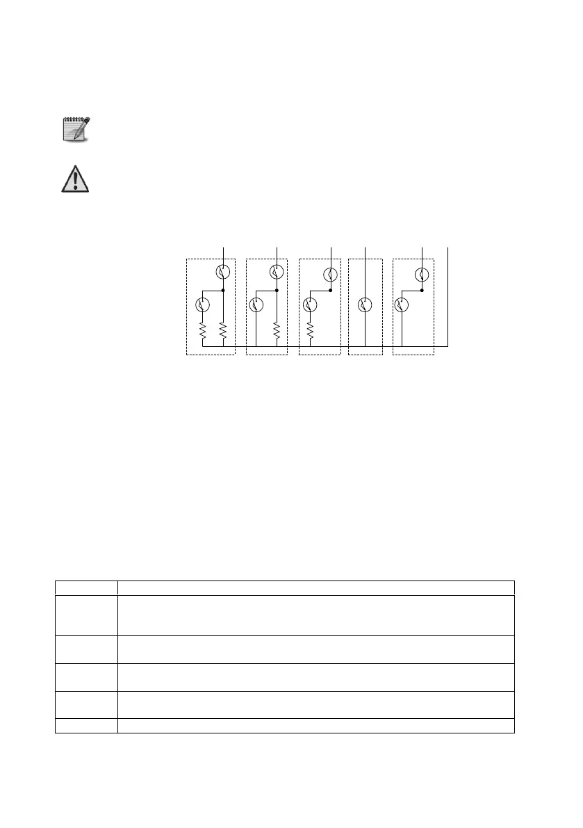
3.1.1 Common zone wiring
Diagram 4. Zone wiring options
The zone state - Normally Open or Normally Close - is set in the “Zone characteristics” screen;
see section 6.4.1.1, on page 50.
3.1.2 EOL resistor loops
To set a zone with one or two EOL resistor loops, refer to “Zone characteristics” screen,
parameter “E” (see section 6.4.1.1, on page 50) and “Key 5: General Parameters”, first
screen, parameter "2" (see section 6.8, on page 65).
3.2 Zone expanders wiring
The following is a brief scan of the zone and output expansion options. A detailed installation
description is found further on.
Local 8 zone expansion card. The zones are always given the numbers 9-16.
See more on section 3.2.4.
The expansion card is connected to the PCB’s “Expansion Card” connector.
Remote 8 zone expander with an onboard relay;
It is connected to the panel over the BUS wires.
Remote 16 zone expander with an onboard relay;
It is connected to the panel over the BUS wires.
24 (in Hunter-Pro 832)/32 (in Hunter-Pro 8144) zone wireless expander.
It also supports 24 key fobs.
Remote 8 relay expander; see more on page 20.
Z
1
Z
2
Z
3
Z
4
Z
5
(
-
)
N
.
O
./
N
.
C
.
,
2
EOL
Resistors
N
.
O
.
,
1
EOL
Resistor
N
.
C
.
,
1
EOL
Resistors
N
.
O
.
N
.
C
.
A
A
A
A
A
T
T
T
T
T
:
Tamper
A
:
Alarm
R
2
R
1
R
1
R
1

 Loading...