Hunter-Pro Series & Captain 8 Installation Guide
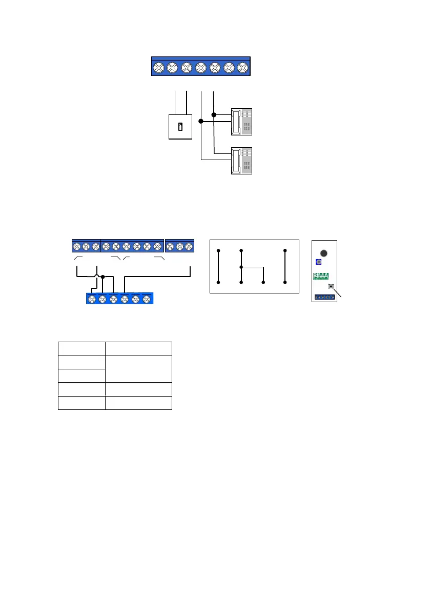
Diagram 37. Telephone Wiring
4.3.7 MIC-200 Microphone
1. Connect the MIC-200 according to the following diagram and table:
Diagram 38. MIC-200 Wiring
2. In the “Zone Responses” menu, set "M- Activate Audio" to '+', in every zone type that
should trigger the microphone in alarm; see section 6.4.2, on page 50.
3. In the "Output configuration" menu, set the polarity of triggering output to "-"; see
section 6.10.4, on page 69.
4. In the "Communication Options" menu, set "Voice Unit" to "+"; see section 6.5.4, on
page 54.
5. The PGM/SMOKE outputs should be triggered by the "Audio Control" output type; see
section 6.10.2, starting page 68.
Z1 Z2 Z3
Z4 Z5 Z6
Z
O
N
E
S
+V
SMOKE PGM
SRN
OUTPUTS
-
1
KEYPAD
OUT LINE
TELEPHONE
SET
-
AUDIO
IN
F
2
Z7 Z8
2 3 4
+
IN
OUT
-
-
-
+
Telephone
line-in
Telephone
set/Fax
Control panel
MIC-200
(-)12(+) CON.OUT TAMP
Tamper
MIC-200
(-)12(+) CON OUT TAMP
+V
SMOKE PGM
SRN
-
1
KEYPAD
OUT
-
AUDIO
IN
2 3 4
+
IN
OUT
-
+
OUTPUTS
(-)
(+)
AUD IN
PGM
(+)
CON OUT

 Loading...