PIPER AIRCRAFT, INC.
PA-28-161, WARRIOR III
MAINTENANCE MANUAL
2D18
24-30-00
2. Alternator System (Electrosystems 28 vdc, 70 amp)
NOTE: In S/N’s 2842257 and up, with Avidyne Entegra installed, see also Standby Alternator, below.
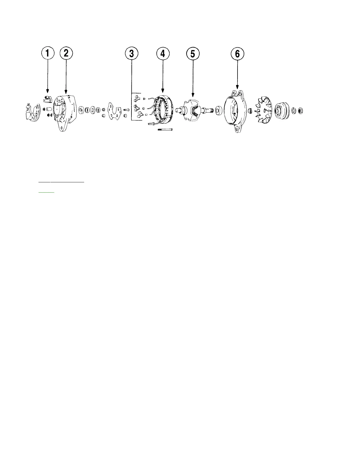
A. Description (Refer to Figure 1.)
The principal alternator components are: brush holder assembly, slip ring end head, rectifiers,
stator, rotor, and drive end head. (The following paragraphs are keyed to Figure 1.)
(1) The brush and holder assembly contains two brushes, two brush springs, a brush holder, and
insulator. One brush is connected to a terminal stud and insulated from ground. The other
brush is connected to ground through brush holder. Brush and holder assembly are easily
removed for inspection or brush replacement.
(2) The slip ring end head provides mounting for rectifiers and rectifier mounting plate, output and
auxiliary terminal studs, and brush and holder assembly. Slip ring end head contains a roller
bearing, outer race assembly, and a grease seal.
(3) The rectifiers used are rated at minimum 150 peak inverse voltage for transient voltage
protection. Three positive rectifiers are mounted in rectifier mounting plate while three negative
rectifiers are mounted in slip ring end head. Each rectifier pair is connected to stator lead with
high temperature solder. Stator leads are anchored to rectifier mounting plate with epoxy
cement for vibration protection.
(4) The stator contains a special lead connected to center of the three phase windings and is used
to activate low voltage warning systems or relays. The stator is treated with a special epoxy
varnish for high temperature resistance.
(5) The rotor contains slip ring end bearing inner race, and spacer on slip ring end of shaft. Rotor
winding and winding leads are specially treated with high temperature epoxy cement to provide
vibration and temperature resistance characteristics. High temperature solder is used to secure
winding leads to slip rings.
(6) The drive end head supports a sealed, pre-lubricated ball bearing in which drive end of rotor
shaft rotates.
PAGE 2
Nov 30/06
Exploded View of Electrosystems Alternator
Figure 1