PIPER AIRCRAFT, INC.
PA-28-161, WARRIOR III
MAINTENANCE MANUAL
PAGE 9
Nov 30/062E1
24-30-00
C. System Check
With electrical equipment off (except master switch) the ammeter will read amount of charging
current demanded by battery. The amount will vary, depending on percentage of battery charge. As
battery is charged, current displayed on ammeter will reduce to approximately two amperes.
Current reading on ammeter will show if alternator system is operating normally.
NOTE: Current reading on ammeter is the load in amperes demanded by the electrical system
from alternator. Check, for example, a condition where battery is demanding 10 amperes
charging current, then switch on landing light. Note value in amperes placarded on circuit
breaker panel for landing light circuit breaker (10 amps) and multiply by 80 percent.You will
arrive at a current of 8 amperes. This is approximate current drawn by the light. When light
is switched on, there will be an increase of current from 10 to 18 amperes on ammeter. As
each unit of electrical equipment is switched on, current will add up and the total, including
battery, will read on ammeter.
For example, the airplane’s maximum continuous load with all equipment on is approximately 60
amperes for 70 ampere alternator. This approximate 60 ampere value, plus approximately two
amperes for a fully charged battery, will appear continuously under these flight conditions. If the
ammeter reading were to go much below this value, under the aforementioned conditions, trouble
with the alternator system would be indicated and corrective action should be taken by switching off
the least essential equipment. Locate faulty components as follows:
(1) Check airplane is positioned so prop blast will not interfere with other operations going on
nearby. Start engine and set throttle for 1000 to 1200 rpm.
(2) Switch on the following loads and observe ammeter output increase as follows:
(a) Rotating beacon - 3 to 6 amps.
(b) Navigation and instrument lights - 4 to 6 amps.
(c) Landing lights - 7 to 9 amps each.
If the alternator does not meet the above readings refer to troubleshooting Chart 1. Follow
troubleshooting procedure outlined on the chart. Check each cause and isolation procedure under a
given trouble.
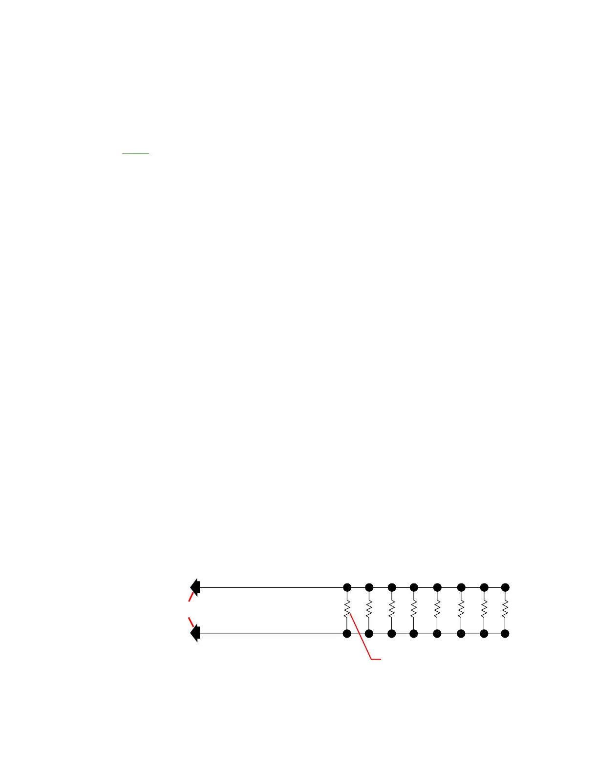
If desired, the load required by test can be simulated by connecting a lamp-bank load consisting of
8 landing lights wired in parallel from main bus (+) to airframe ground (-), or 8, 3-ohm, 100-watt
resistors. (Refer to Figure 2.)
Lamp Bank Load
Figure 2