PIPER AIRCRAFT, INC.
PA-28-161, WARRIOR III
MAINTENANCE MANUAL
PAGE 3
Nov 30/06
2K11
28-40-00
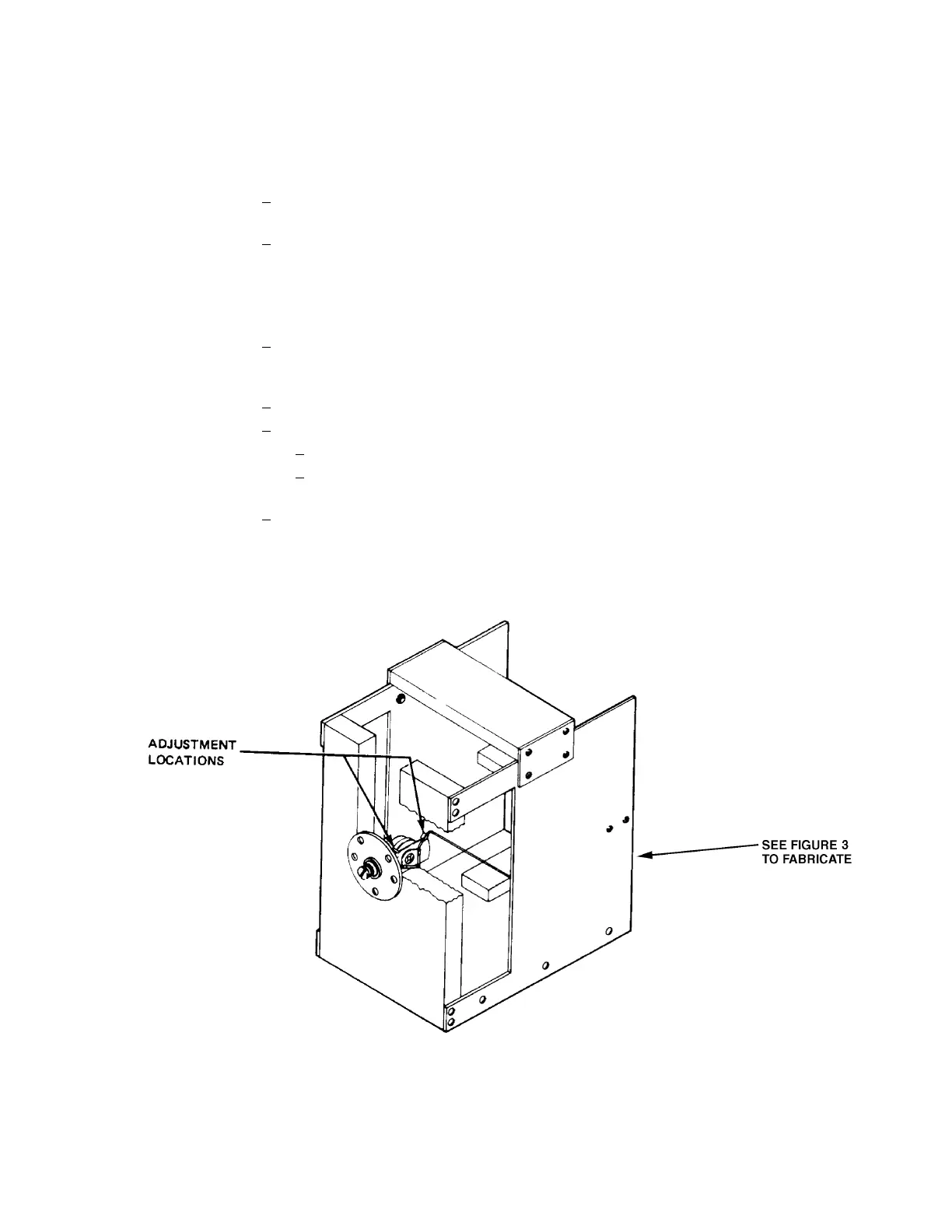
Fuel Quantity Sender Check
Figure 1
(3) Check and Adjustment
(a) Remove transmitter unit to be checked from the fuel tank.
(b) Check and adjust transmitter unit float position as follows:
1
Fasten unit to a fabricated checking jig with washer and nuts as shown in Figure 1.
(Fabricate jig per Figure 3 dimensions.)
2
Check resistance with the float just touching the top, back of a 0.27 inch spacer.
Resistance of the sending unit is 3 ohms, ± 0.5 ohm. If the resistance of the sending
unit is not in this range, adjust arm of the float assembly by gently bending it as
shown in Figure 1. The entire float must be kept horizontal to the base of the fixture.
(c) Check transmitter unit for correct resistance and dead spots as follows:
1 Remove sending unit from the checking fixture and connect it to an ohmmeter. Allow
float arm to rest on the bottom mechanical stop. The resistance must read 0, ± 0.5
ohms .
2 Move float arm to its upper mechanical stop. The resistance must be 45, ± 2 ohms.
3
To check for dead spots:
a
Slowly moving float arm from bottom stop, to upper stop, and back.
b Check that ohmmeter moves steadily up and down scale without fluctuation as
float arm is moved.
4
If any resistance is not correct, or any dead spots are found, replace sending unit.