5. Voltage Regulator
The Lamar voltage regulator is a fully transistorized unit. The components are encapsulated in epoxy,
making field repair of the unit impractical. Before performing any of the following checks verify proper
functioning of the alternator per manufacturer’s instructions. If it does not meet the specifications, the
alternator must be replaced.
CAUTION: DO NOT CONNECT THE VOLTMETER ACROSS THE BATTERY, BECAUSE THE
REGULATOR IS DESIGNED TO COMPENSATE FOR RESISTANCE CONTAINED WITHIN
THE WIRING HARNESS.
A. Testing
(1) Use only a good quality, adjustable dc power source.
CAUTION
: ALL TESTS MUST BE ACCOMPLISHED WITH THE REGULATOR OUT OF THE
CIRCUIT.
(2) Use a quality, accurate voltmeter with at least a 35-volt scale.
CA
UTION: AMBIENT TEMPERATURES SURROUNDING VOLTAGE REGULATOR MUST
BE BETWEEN 50°F AND 100°F.
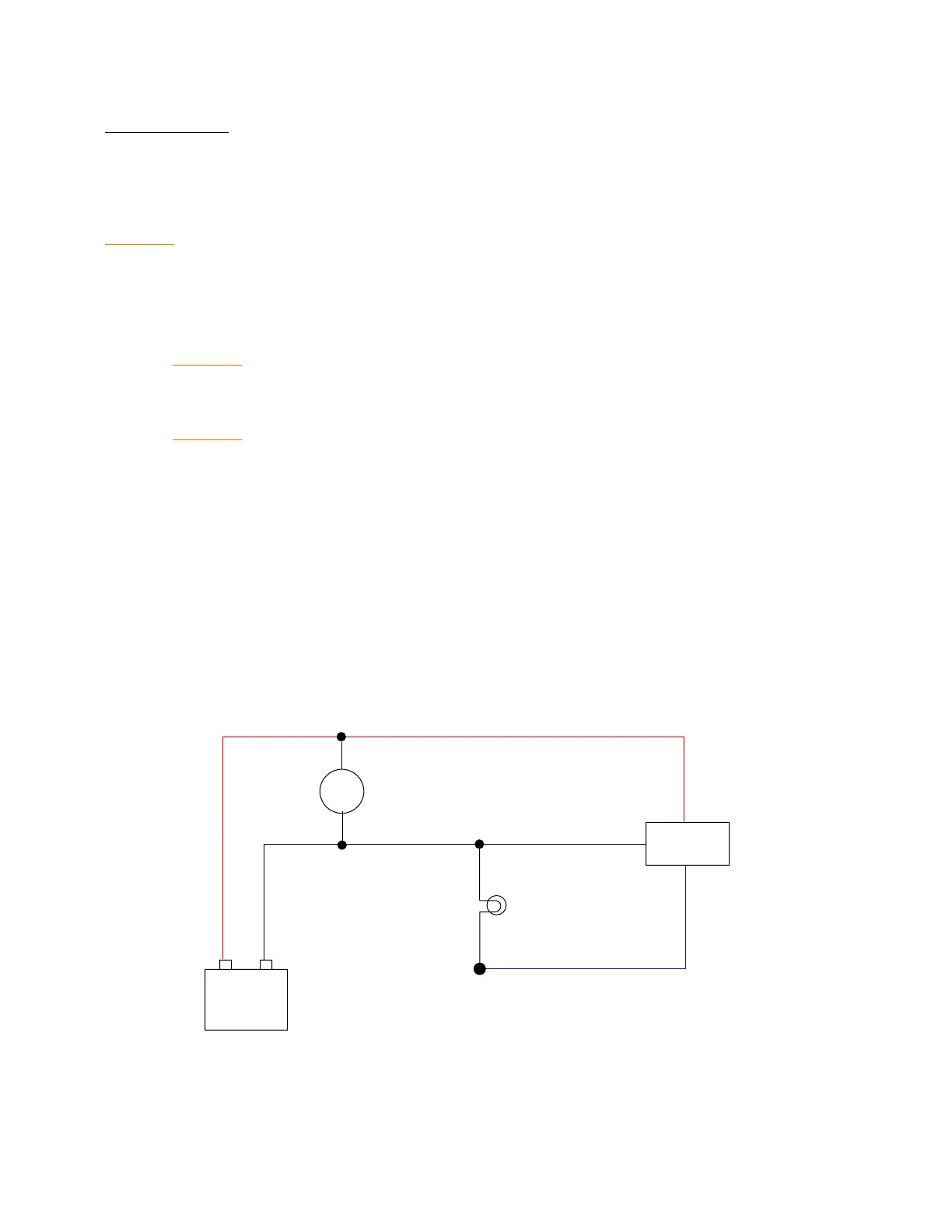
(3) Voltmeter connections (Refer to Figure 6.)
(a) Connect positive voltmeter lead to red wire (supply) at regulator harness connector or
wire.
(b) Connect negative voltmeter lead to regulator ground wire (black).
(4) Light Bulb Connections.
(a) Connect one bulb lead to blue wire (field) at regulator harness connector or wire.
(b) Connect other bulb lead to regulator ground wire (black).