Power Unit
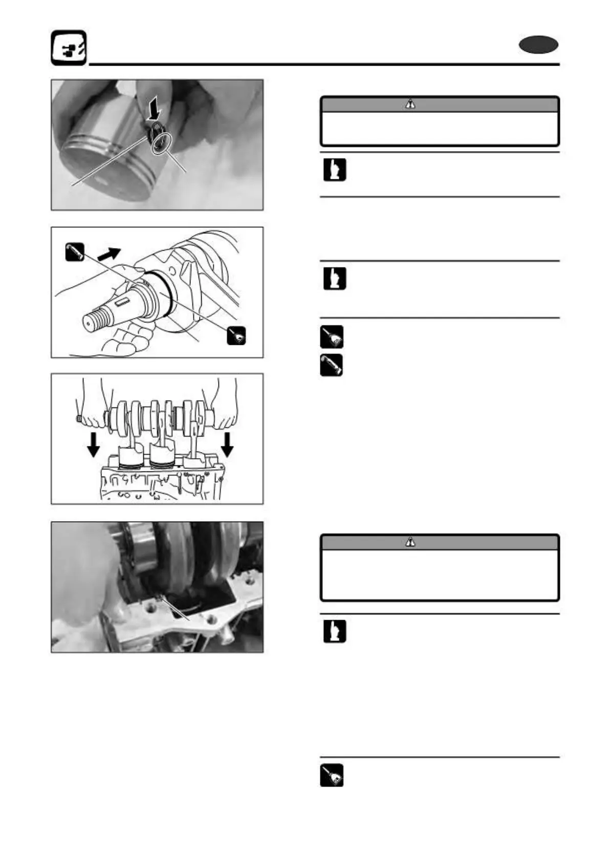
3) Fit piston pin clip 7 as shown.
CAUTION
Take care not to scratch to piston wall,
when fit piston pin clip.
Set the piston pin clip so that the gap of the clip is
a
7
LIT
LIT
1
2 1
3
at the opposite side of the opening a located in
the piston pin clip groove.
21) Assembling Power Unit Parts
1. Install main bearing (upper) 1 to crank shaft ass’y.
· Face the marking on the bearing to flywheel
side.
· Apply LIT grease to the oil seal lip.
· Use new O ring.
2st OIL
2st
2st
2st OIL
LIT
LIT
2. Install crank shaft ass'y to cylinder.
Apply genuine engine oil to the following parts before
assembling them.
· Big End of Connecting Rod
· Small End of Connecting Rod
· Main Bearing and ball bearing
· Piston Ring and Entire Circumference of Piston, and
Entire Cylinder Wall
· O Ring of Upper Bearing
CAUTION
When the piston skirt enters into cylinder
liner, thrust plate 2 is inserted in groove,
and then crank shaft is lowered slowly.
2
· When installing crank shaft ass'y, lower the ass'y
gradually so that crank shaft is held parallel with the
cylinder face.
· Insert pistons one by one while confirming that
each piston enters vertically in the cylinder liner.
Pistons can be inserted easier while moving
them up and down a little.
· Put a piece of round bar or pipe 3 of ø13.5 mm
(0.532 in) in the drive shaft opening to make it
easier to hold.
2st OIL
2st
5-74
2st X50D2 2011