Bracket
GB
3
0
3
1342
1342
1 2
a
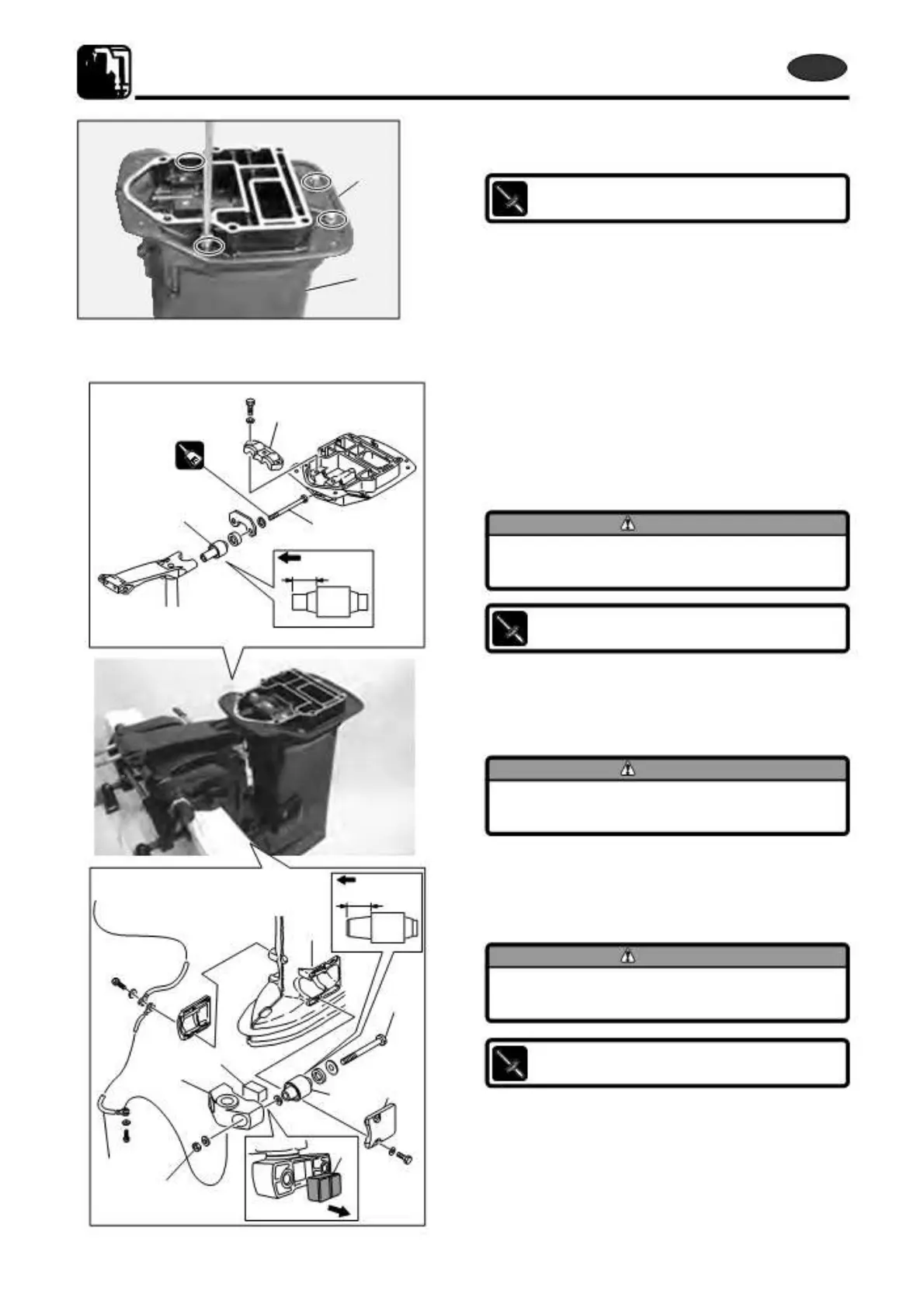
7.
Install engine base 3 to drive shaft housing 0 by
tightening installation bolts to specified torque.
Engine Base Bolts :
20 N · m (14.5 lb · ft) [2.0 kgf · m]
9)
Assembling Rubber Mounting
When assembling drive shaft housing parts, reverse the
disassembling procedure.
1.
Install upper mount 1 and tighten bolts 2 to specified
torque.
CAUTION
Install the mount with the side of longer
size a facing forward.
Upper Rubber Mount Bolts 2 :
29 N · m (22 lb · ft) [2.9 kgf · m]
2. Install upper mount holding plate 3.
3. Install dumper rubber 5 to mount bracket 4.
CAUTION
Install dumper rubber with the grooved
side c facing drive shaft housing.
b
4. Put lower rubber mount 6 to drive shaft housing and
tighten bolts 7 and nuts 8 to specified torque.
CAUTION
Install the mount with the side of longer
7
size b facing forward.
5
Lower Rubber Mount Bolt and Nut
7
and
8
:
4
41 N · m (27 lb · ft) [4.2 kgf · m]
6
9
5. Install mount holding plates 9.
c
0
6. Attach ground wire 0.
8
7-38
2st X50D2 2011
 Loading...