Electrical System
RO
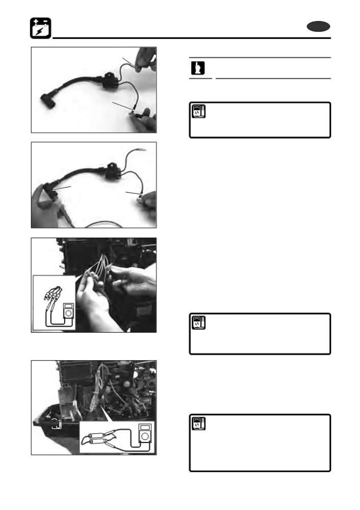
a
b
c
b
3) Inspection of Ignition Coils
This test can be made without removing parts.
1.
Measure ignition coil resistance. Replace if other than
specified value.
Ignition Coil Resistance :
Primary Side : Between a and b 0.4 - 0.6 Ω
Secondary Side : Between c and b 6.8 - 10.2 kΩ
(without plug cap)
4) Inspection of Pulser Coil
• Measurement of resistance
1. Open electrical bracket.
2. Disconnect all connectors from coil plate ass`y, and
measure resistance between terminals.
Replace pulser coil if the resistance is out of specified
range.
Pulser Coil Resistance :
Blue (L)/White (W) - Black (B) #1
White (W)/Black (B) - Black (B) #2
White (W)/Red (R) - Black (B) #3
160 - 220 Ω
• Measurement of peak volts
1. Connect Peak Voltage adapter to pulser coil connectors.
2. Measure peak volts at shown below.
Replace pulser coil or check connection of wire harness if the
peak volts out of specified range.
Pulser Coil Peak Volts: (Reference)
Blue (L)/White (W) - Black (B) #1
White (W)/Black (B) - Black (B) #2
White (W)/Red (R) - Black (B) #3
3 V at cranking
7 V at idling
19 V at 1.500 r/min
8-14
2st 50D2 2011