Electrical System
GB
6) Measure peak voltage at engine cranking or engine
starting.
• When measuring peak voltage at engine
cranking, remove spark plug cap from spark
plug
and spark plug is attached.
• Variation occurs in output value with cranking
speed.
• For manual start model:
Cranking speed is unstable, cranking
measurement makes reference value.
• Because numerical value of the data of each
model statement page is the lower limit, if it is
above this, as for good condition.
• The faulty part it specifies, input voltage being
properly, if there is a unit whose output voltage is
not properly that is the faulty part.
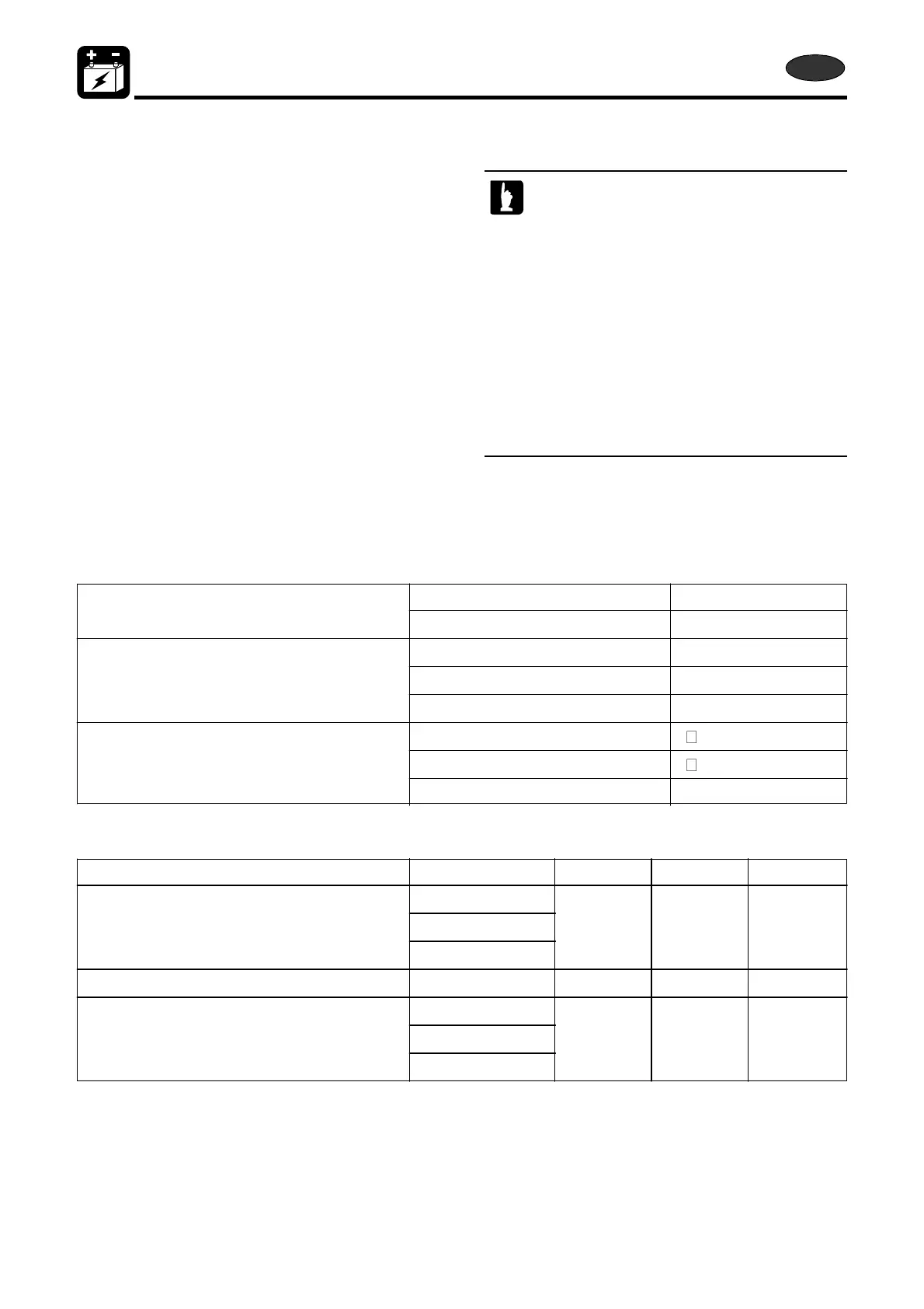
4. Inspection date
Resistance test reference
Ignition coil Primary 0.4 ~ 0.6Ω
Secondary 6.8 ~ 10.2 kΩ
Pulser Coil L/W - B #1 160 ~ 220Ω
WB - B #2 160 ~ 220Ω
WR - B #3 160 ~ 220Ω
Exciter Coil W/G - B
Or - B
Or - W/G 520 ~ 720Ω
Peak voltage out put test reference
Cranking Idling 1500r/min
Pulser Coil L/W - B #1
WB - B #2 3V 7V 19V
WR - B #3
Exciter Coil Or - W/G 185V 210V 210V
C.D unit B/W - B
B/R - B 160V 180V 180V
B/G - B
8-10
2st 50D2 2011