Lower Unit
GB
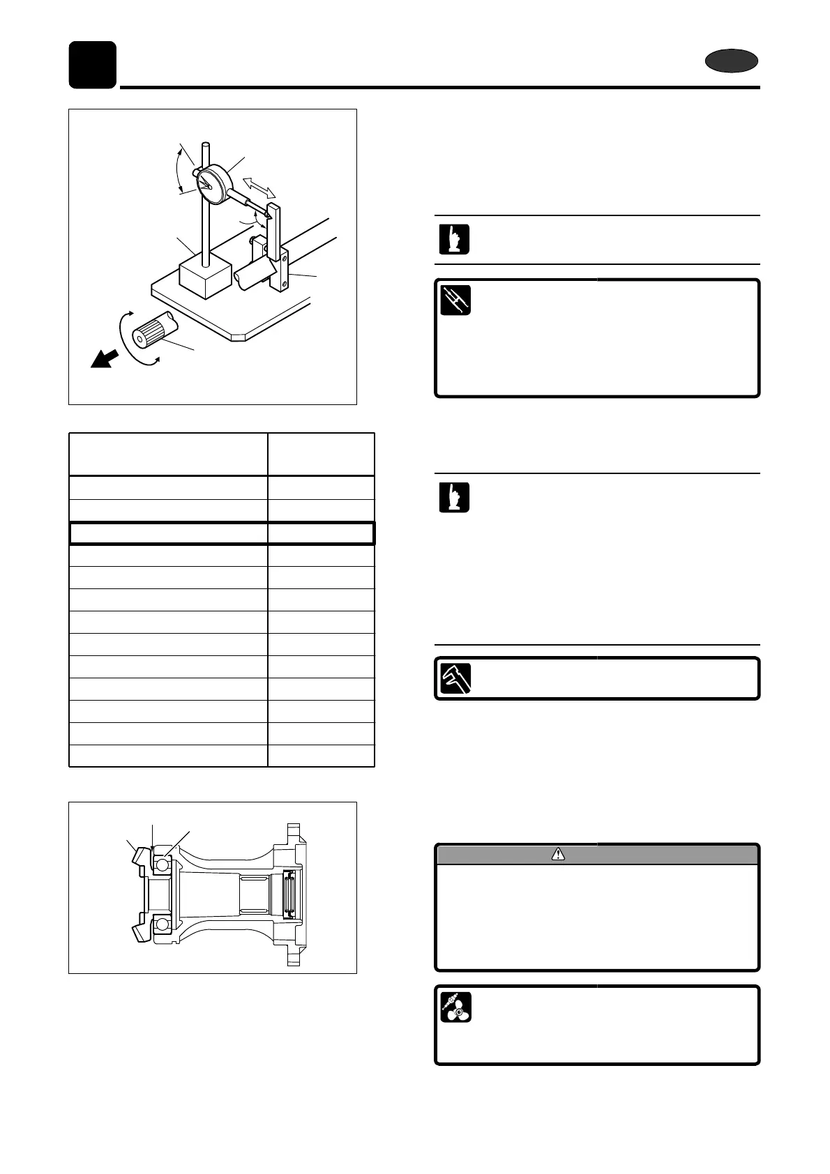
5. Attach backlash measuring tool clamp e to drive shaft.
e
6. Turn drive shaft w clockwise / counterclockwise slowly
while pulling it up, and read change of dial gauge
indication.
r
When measuring, contact dial gauge tip to inside
of V groove located in the clamp ass’y.
w
Backlash Measuring Tool Clamp e :
P/N. 3B7-72720-0
Dial Gauge
r
:
q
Commercially Available Item
Magnetic Stand t :
Commercially Available Item
∫
Shim Thickness : mm (in )
å Dial Gauge Reading : mm (in)
+ means addition of shim/-
means removal of shim
0.00 0.18 0.00 0.0071 0.10 0.0039
0.19 0.28 0.0075 0.0110 0.05 0.0019
0.29 0.58 0.0114 0.0228 0.00
0.59 0.67 0.0232 0.0264 0.05 0.0019
7.
Select shim thickness required based on the change of
dial gauge indication and the table shown.
· Confirm dial gauge reading and adjust backlash
by using thickness of shim selected.
· Measure backlash several times while changing
gear teeth contact position.
· When measuring backlash, make drive shaft
0.68 0.83 0.0268 0.0327 0.10 0.0039 pulling up force equal among the measurements.
0.84 0.99 0.0331 0.0390 0.15 0.0059
1.00 1.15 0.0394 0.0453 0.20 0.0078
1.16 1.31 0.0457 0.0516 0.25 0.0098
1.32 1.47 0.0520 0.0579 0.30 0.0118
· This work can be made easier when the opening
of gear case of propeller shaft side is faced
upward and fixed horizontally with a holder.
Proper Backlash :
1.48 1.63 0.0583 0.0642 0.35 0.0137
0.29 - 0.58 mm (0.0114 - 0.0228 in)
1.64 1.79 0.0646 0.0705 0.40 0.0157
1.80 1.95 0.0709 0.0768 0.45 0.0177
1.96 2.11 0.0772 0.0831 0.50 0.0196
b
t
8.
y
Add shim(s) into gap b between reverse (C) gear t and
bearing y if necessary.
CAUTION
For removal or installation of reverse (C)
gear, refer to;
“Disassembly of Propeller Shaft Housing
Ass’y” or “Assembly of Lower Unit” in
Chapter 6 respectively.
Type of Shims :
0.1 mm (0.0039 in) P/N. 353-64038-0
0.15 mm (0.0059 in) P/N. 353-64037-0
0.3 mm (0.0118 in) P/N. 353-64036-0
6-90
2st 50D2 2