Chapter 1: Installation and Initial Configuration
The top and bottom bars on the LCD display may be yellow or red,
depending on the type(s) of available alerts. See
Operating the
Dot-Matrix LCD Display
(on page 36).
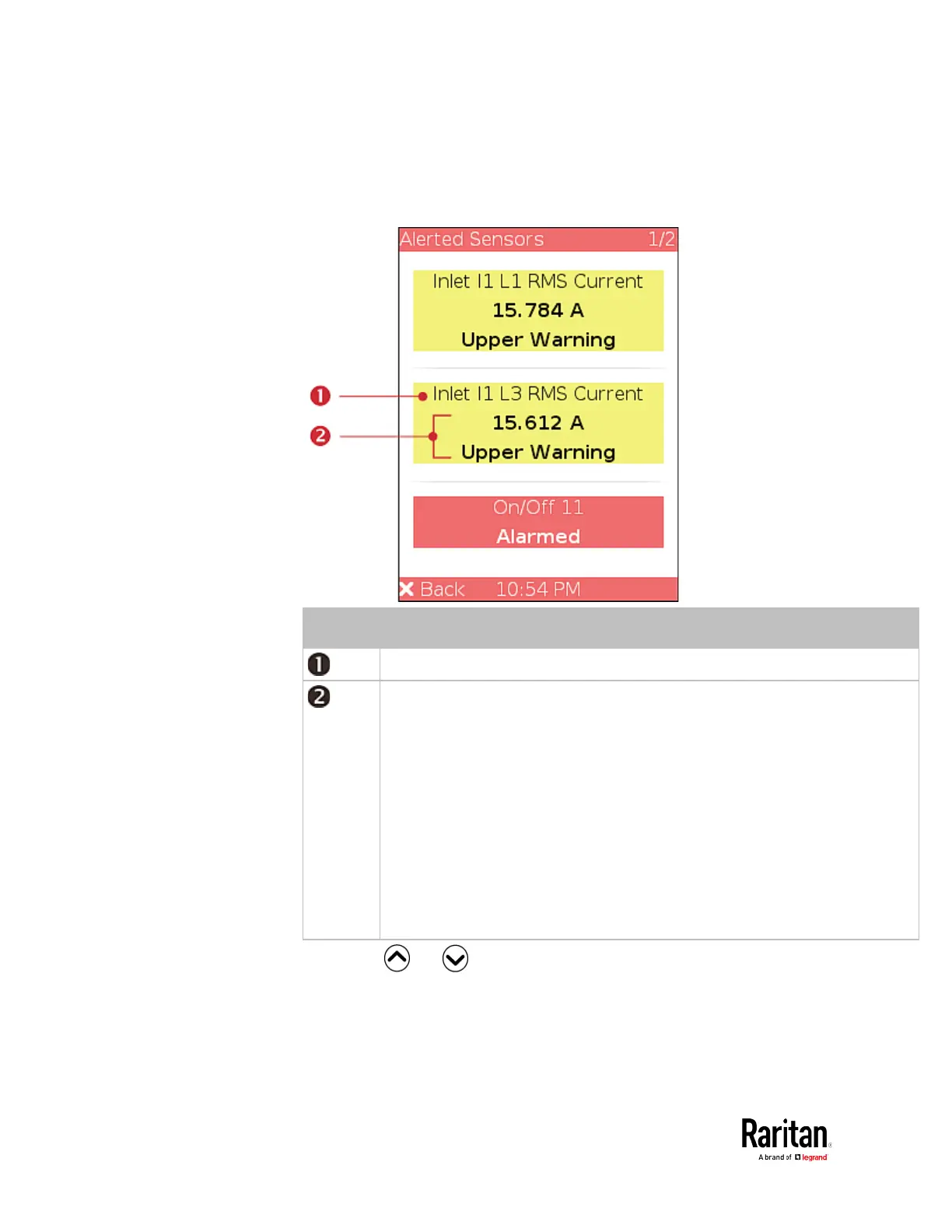
Sensor names.
Sensor readings and/or states.
A numeric sensor shows both the reading and state. A state sensor or
actuator shows the state only.
Available states are listed below. For further information, see
(on page 123).
Alarmed
Lower Critical = below lower critical
Lower Warning = below lower warning
Upper Warning = above upper warning
Upper Critical = above upper critical
Open (for overcurrent protectors)
3. Press or to view additional pages. When there are
multiple pages, page numbers appear in the top-right corner of the
display.
 Loading...