RL78/F13, F14 CHAPTER 17 LIN/UART MODULE (RLIN3)
R01UH0368EJ0210 Rev.2.10 1125
Dec 10, 2015
(16) LIN/UART Control Register (LCUCn)
Address: F06CEH
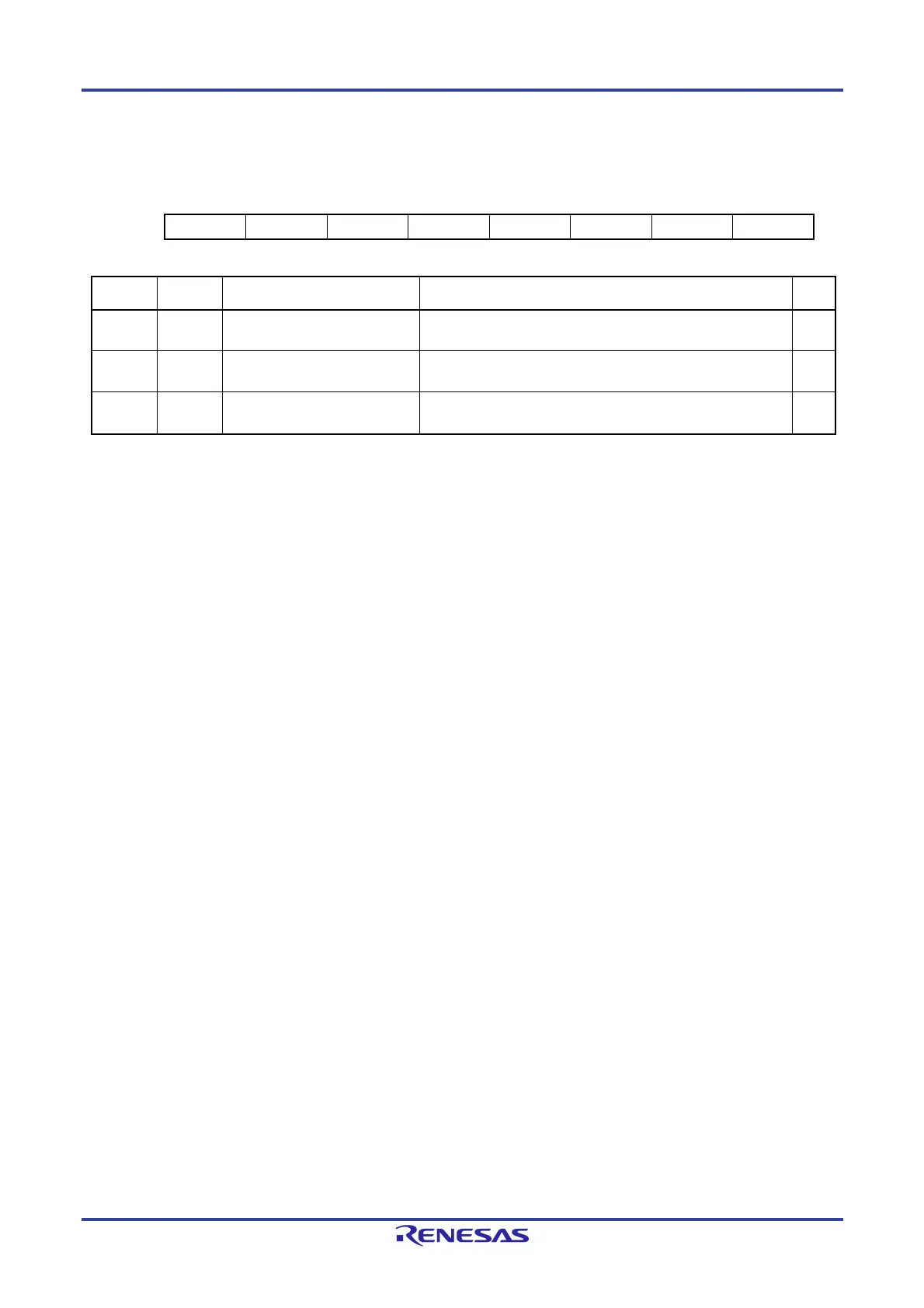
7 6 5 4 3 2 1 0
— — — — — — OM1 OM0
Value after reset:
0 0 0 0 0 0 0 0
Bit Symbol Bit Name Function R/W
0 OM0 LIN Reset 0: LIN reset mode is caused.
1: LIN reset mode is canceled.
R/W
1 OM1 LIN Mode Select 0: LIN wake-up mode is caused.
1: LIN operation mode is caused.
R/W
7 to 2 — Reserved These bits are always read as 0. The write value should always
be 0.
R/W
Set the LCUCn register to 01H to cause a transition to LIN wake-up mode after canceling LIN reset mode, and set the
LCUCn register to 03H to cause a transition to LIN operation mode.
In LIN self-test mode, set the LCUCn register to 03H after a transition to LIN self-test mode is completed.
After a value is written to this register, confirm that the value written is actually indicated in the LMSTn register before writing
another value.
OM0 bit (LIN reset bit)
The OM0 bit selects either causing a transition to LIN reset mode or canceling LIN reset mode.
With 0 set, LIN reset mode is caused.
With 1 set, LIN reset mode is canceled.
OM1 bit (LIN mode select bit)
The OM1 bit selects the specific operation mode (either LIN wake-up mode or LIN operation mode) after canceling LIN reset
mode.
With 0 set, LIN wake-up mode is caused.
With 1 set, LIN operation mode is caused.
This register is valid only when the OMM0 bit in the LMSTn register is 1.
Writing a value to this bit is disabled while the FTS bit in the LTRCn register is 1.
 Loading...


