RL78/F13, F14 CHAPTER 16 SERIAL INTERFACE IICA
R01UH0368EJ0210 Rev.2.10 1065
Dec 10, 2015
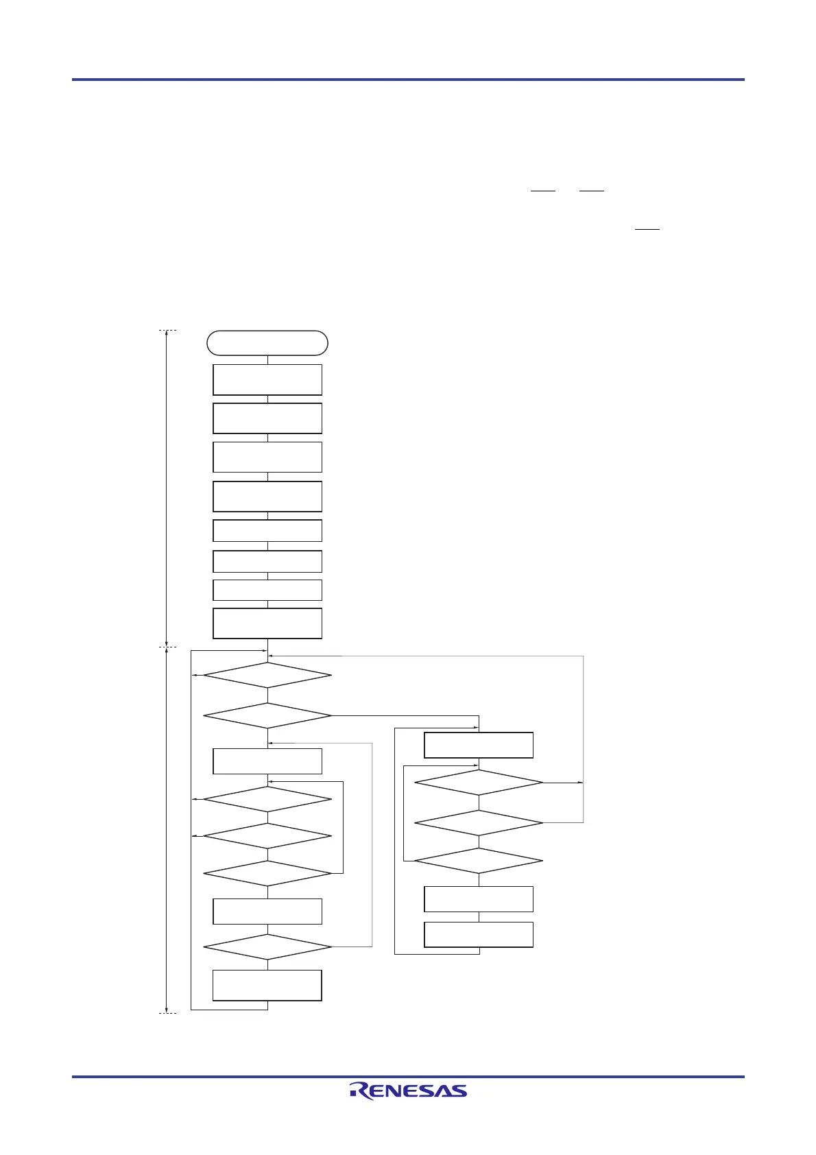
The main processing of the slave operation is explained next.
Start serial interface IICA and wait until communication is enabled. When communication is enabled, execute
communication by using the communication mode flag and ready flag (processing of the stop condition and start
condition is performed by an interrupt. Here, check the status by using the flags).
The transmission operation is repeated until the master no longer returns ACK. If ACK is not returned from the
master, communication is completed.
For reception, the necessary amount of data is received. When communication is completed, ACK is not returned
as the next data. After that, the master generates a stop condition or restart condition. Exit from the communication
status occurs in this way.
Figure 16-31. Slave Operation Flowchart (1)
Remark Conform to the specifications of the product that is in communication, regarding the transmission and reception
formats.
Yes
Yes
Yes
Yes
Yes
Yes
Yes
No
No
No
No
No
No
WREL0 = 1
ACKD0 = 1?
No
Yes
No
Yes
No
START
Communication
mode flag = 1?
Communication
mode flag = 1?
Communication
direction flag = 1?
Ready flag = 1?
Communication
direction flag = 1?
Reading IICA0
Clearing ready flag
Clearing ready flag
Communication
direction flag = 1?
Clearing communication
mode flag
WREL0 = 1
Writing IICA0
SVA0 ← XXH
Sets a local address.
IICWL0, IICWH0 ← XXH
Selects a transfer clock.
IICF0 ← 0XH
Setting IICRSV0
Sets a start condition.
Starts
transmission.
Starts
reception.
Communication
mode flag = 1?
Ready flag = 1?
Setting port
Setting port
Communication processing
Initial setting
Setting of the port used alternatively as the pin to be used.
First, set the port to input mode and the output latch to 0 (see 16.3.8 Port mode register 6 (PM6)).
Set the port from input mode to output mode and enable the output of the I
2
C bus
(see 16.3.8 Port mode register 6 (PM6)).
IICCTL00 ← 0XX011XXB
ACKE0 = WTIM0 = 1, SPI0 = 0
Setting
IICCTL01
IICCTL00 ← 1XX011XXB
IICE0 = 1
 Loading...


