RL78/F13, F14 CHAPTER 16 SERIAL INTERFACE IICA
R01UH0368EJ0210 Rev.2.10 1066
Dec 10, 2015
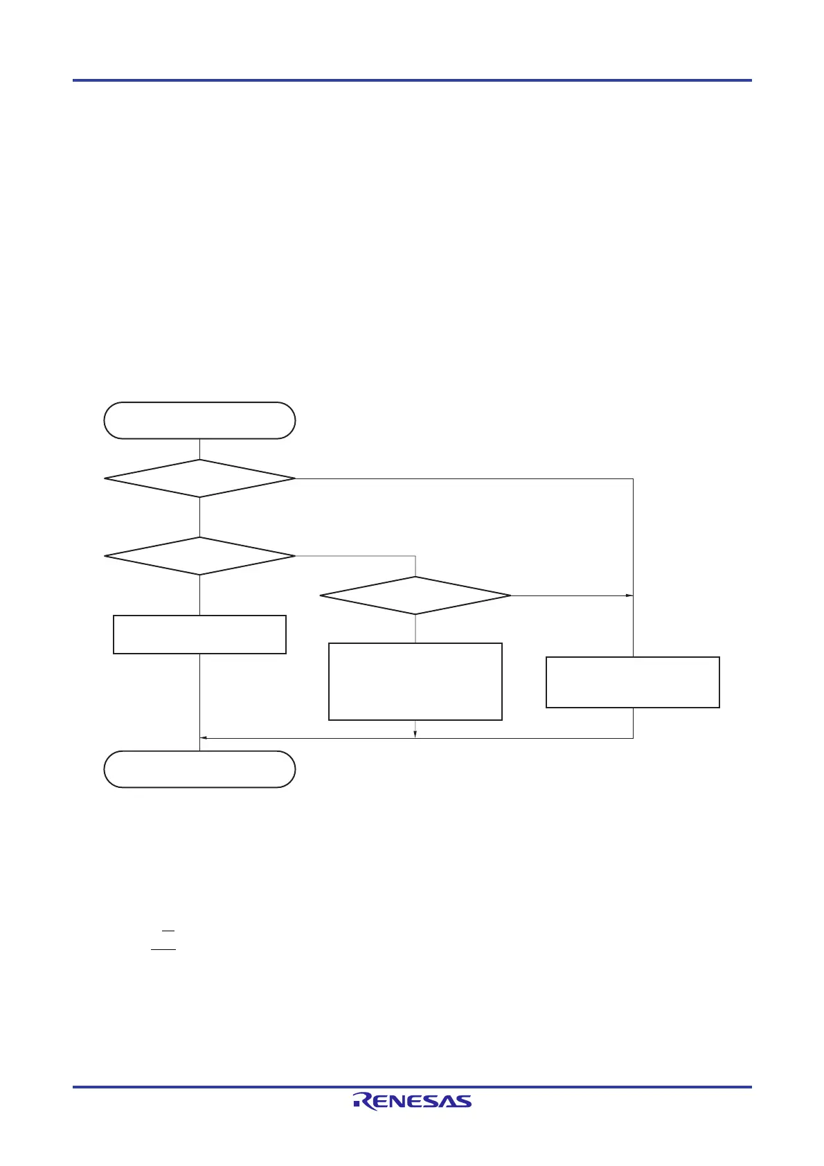
An example of the processing procedure of the slave with the INTIICA0 interrupt is explained below (processing is
performed assuming that no extension code is used). The INTIICA0 interrupt checks the status, and the following
operations are performed.
<1> Communication is stopped if the stop condition is issued.
<2> If the start condition is issued, the address is checked and communication is completed if the address does not
match. If the address matches, the communication mode is set, wait is cancelled, and processing returns from
the interrupt (the ready flag is cleared).
<3> For data transmit/receive, only the ready flag is set. Processing returns from the interrupt with the I
2
C bus
remaining in the wait state.
Remark <1> to <3> above correspond to <1> to <3> in Figure 16-31 Slave Operation Flowchart (2).
Figure 16-31. Slave Operation Flowchart (2)
16.5.17 Timing of I
2
C interrupt request (INTIICA0) occurrence
The timing of transmitting or receiving data and generation of interrupt request signal INTIICA0, and the value of the IICA
status register 0 (IICS0) when the INTIICA0 signal is generated are shown below.
Remark ST: Start condition
AD6 to AD0: Address
R/W: Transfer direction specification
ACK: Acknowledge
D7 to D0: Data
SP: Stop condition
Yes
Yes
Yes
No
No
No
INTIICA0 generated
Set ready flag
Interrupt servicing completed
SPD0 = 1?
STD0 = 1?
COI0 = 1?
Communication direction flag
← TRC0
Set communication mode flag
Clear ready flag
Clear communication direction
flag, ready flag, and
communication mode flag
<1>
<2>
<3>
 Loading...


