RL78/F13, F14 CHAPTER 16 SERIAL INTERFACE IICA
R01UH0368EJ0210 Rev.2.10 1068
Dec 10, 2015
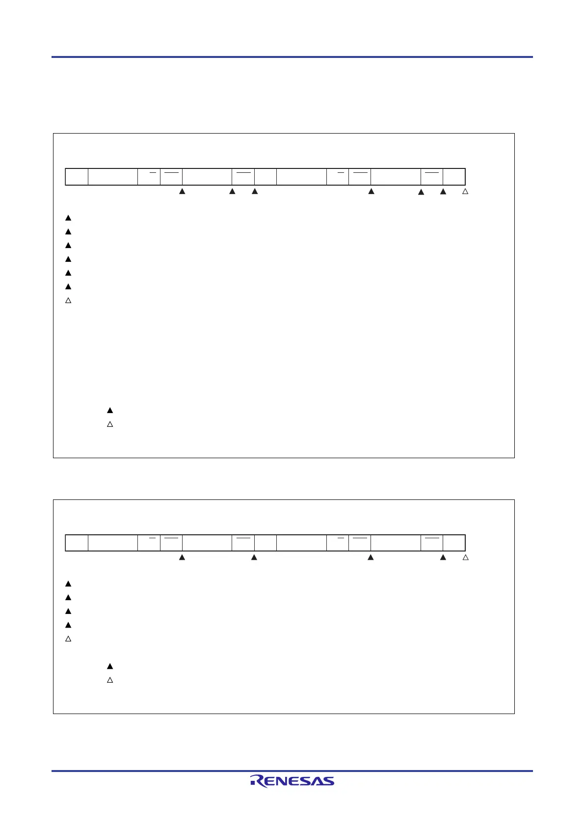
(b) Start ~ Address ~ Data ~ Start ~ Address ~ Data ~ Stop (restart)
(i) When WTIM0 = 0
1: IICS0 = 1000×110B
2: IICS0 = 1000×000B (Sets the WTIM0 bit to 1)
Note 1
3: IICS0 = 1000××00B (Clears the WTIM0 bit to 0
Note 2
, sets the STT0 bit to 1)
4: IICS0 = 1000×110B
5: IICS0 = 1000×000B (Sets the WTIM0 bit to 1)
Note 3
6: IICS0 = 1000××00B (Sets the SPT0 bit to 1)
7: IICS0 = 00000001B
Notes 1. To generate a start condition, set the WTIM0 bit to 1 and change the timing for generating the INTIICA0
interrupt request signal.
2. Clear the WTIM0 bit to 0 to restore the original setting.
3. To generate a stop condition, set the WTIM0 bit to 1 and change the timing for generating the INTIICA0
interrupt request signal.
Remark : Always generated
: Generated only when SPIE0 = 1
×: Don’t care
(ii) When WTIM0 = 1
1: IICS0 = 1000×110B
2: IICS0 = 1000××00B (Sets the STT0 bit to 1)
3: IICS0 = 1000×110B
4: IICS0 = 1000××00B (Sets the SPT0 bit to 1)
5: IICS0 = 00000001B
Remark : Always generated
: Generated only when SPIE0 = 1
×: Don’t care
ST AD6 to AD0 R/W ACK D7 to D0 AD6 to AD0ACK ACK SPST R/W D7 to D0 ACK
STT0 = 1
↓
SPT0 = 1
↓
3 4 7 2
1
5
6
ST AD6 to AD0 R/W ACK D7 to D0 AD6 to AD0ACK ACK SPST R/W D7 to D0 ACK
STT0 = 1
↓
SPT0 = 1
↓
3 4 5 2
1
 Loading...


