RL78/F13, F14 CHAPTER 17 LIN/UART MODULE (RLIN3)
R01UH0368EJ0210 Rev.2.10 1228
Dec 10, 2015
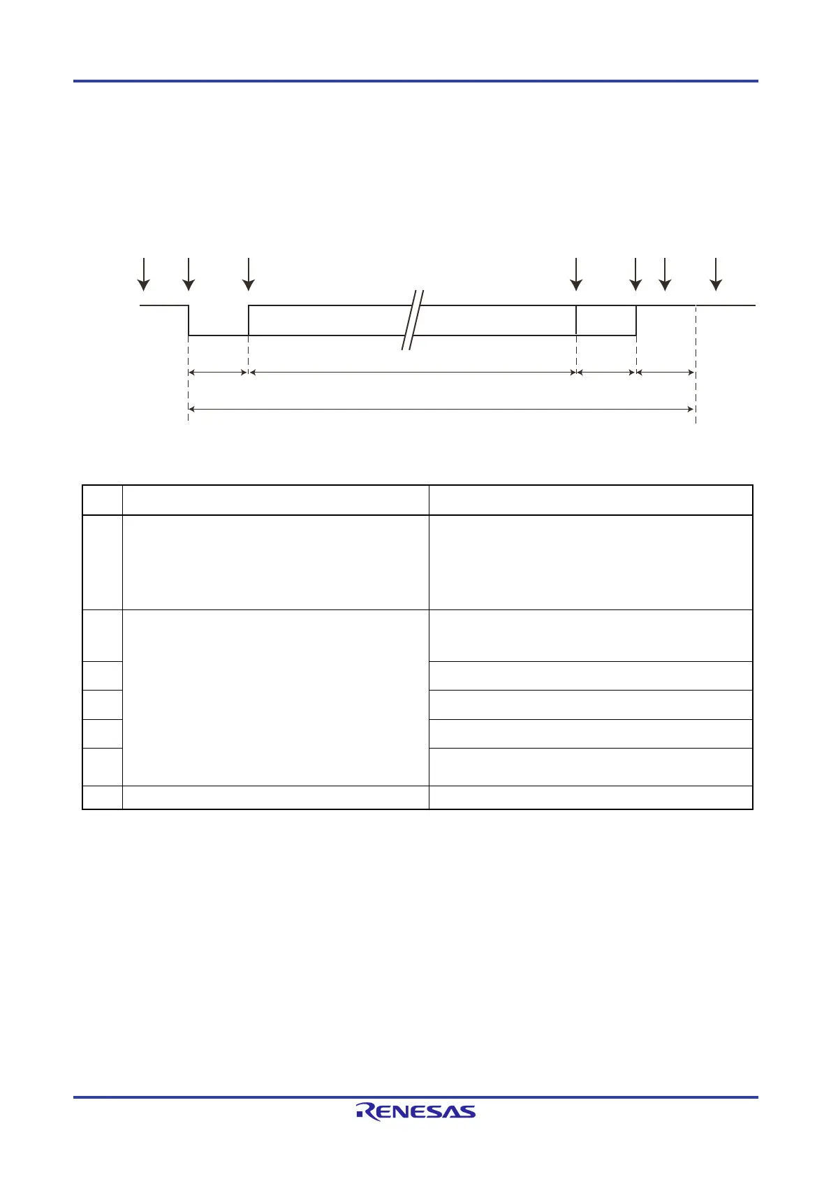
(2) Reception
Figure 17-26 shows the LIN/UART module (in UART mode) reception operation. Table 17-20 shows the LIN/UART module
(in UART mode) reception processing.
Figure 17-26. LIN/UART Module (in UART Mode) Reception Operation
Table 17-20.
LIN/UART Module (in UART Mode) Reception Processing
Step Software processing LIN/UART module processing
(1)
Sets a baud rate.
Sets noise filter ON/OFF.
Sets error detection enable.
Sets data format.
Clears the LIN/UART module from LIN reset mode.
Sets the receive enable bit (UROE bit) to 1.
Waits for reception enable state switching by software.
Waits for detection of a start bit.
(2) Waits for an interrupt request.
Waits for a falling edge from the reception pin, and detects
a start bit.
Sets the reception status flag.
(3) Receives data.
(4) Receives a parity bit when parity is used.
(5) Receives only 1 stop bit.
(6)
Outputs a successful reception interrupt.
Clears the reception status flag.
(7) Checks the LSTn register and clears flags. Waits for a falling edge from the reception pin.
n = 0, 1
Idle
stop bits
0 or 1
parity bit
7, 8, or 9 data bits
UART frame
Idle Start bit
LRXDn
n = 0, 1
(1) (3)(2) (4) (6) (7)(5)
 Loading...


