RL78/F13, F14 CHAPTER 19 DTC
R01UH0368EJ0210 Rev.2.10 1452
Dec 10, 2015
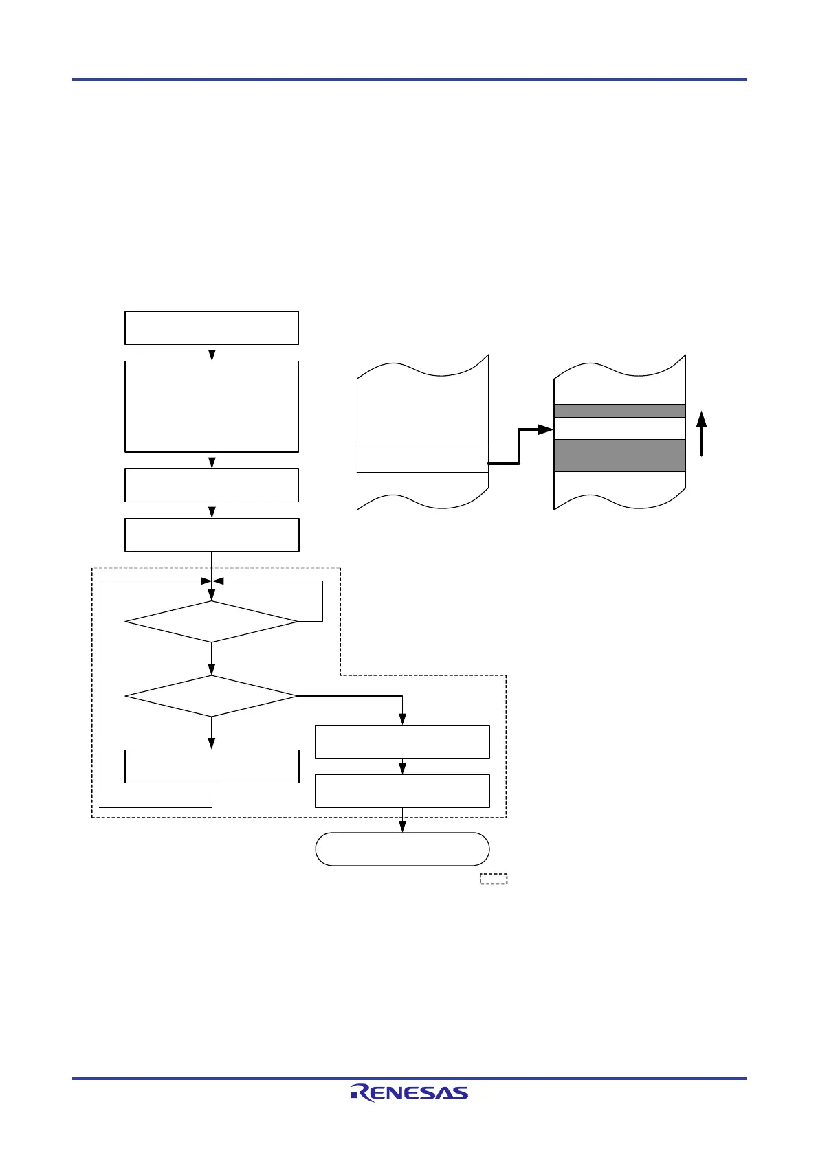
(1) Example 1 of using normal mode: Consecutively capturing A/D conversion results
The DTC is activated by an A/D conversion end interrupt and the value of the A/D conversion result register is
transferred to RAM.
The vector address is FFB09H and control data is allocated at FFBA0H to FFBA7H.
An A/D interrupt is assigned to source number 9.
Transfers 2-byte data of the A/D conversion result register (FFF1EH, FFF1FH) to 80 bytes of FFD80H to FFDCFH
of RAM.
Figure 19-22. Example 1 of Using Normal Mode: Consecutively Capturing A/D Conversion Results
A/D conversion result
register
RAM
DTCBAR = FBH
Vector address (FFB09H) = A0H
DTCCR12 (FFBA0H) = 48H
DTBLS12 (FFBA1H) = 01H
DTCCT12 (FFBA2H) = 50H
DTRLD12 (FFBA3H) = 50H
DTSAR12 (FFBA4H) = FF1EH
DTDAR12 (FFBA6H) = FD80H
DTCEN16 = 1
Starting A/D conversion
Interrupt handling
No
DTCCT12 = 01H?
Data transfer
Yes
Yes
No
Occurrence of interrupt
corresponding to source number 9
DTCEN16 = 0
Data transfer
The processing shown inside the dotted
line is automatically executed by the DTC.
The data of DTRLD12 does not affect DTC transfer operation because of normal mode.
FDCEH
FD80H
A/D conversion
end interrupt?
 Loading...


