RL78/F13, F14 CHAPTER 21 INTERRUPT FUNCTIONS
R01UH0368EJ0210 Rev.2.10 1491
Dec 10, 2015
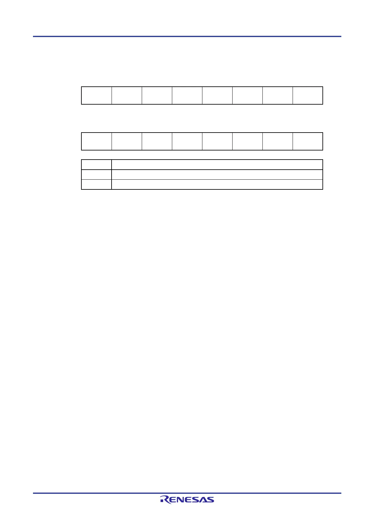
Figure 21-2. Format of Interrupt Request Flag Registers (IF0L, IF0H, IF1L, IF1H, IF2L, IF2H, IF3L) (2/2)
ddress: FFFD1H After reset: 00H R/W
Symbol <7> <6> 5 <4> <3> <2> <1> <0>
IF2H FLIF TMIF13 TMIF12 TMIF11 TMIF10 CANGERRIF
CANGREFRI
F
CAN0TRMIF
ddress: FFFD2H After reset: 00H R/W
Symbol <7> <6> <5> <4> <3> <2> <1> <0>
IF3L TMIF17 TMIF16 TMIF15 TMIF14
LIN1STAIF
LIN1IF
LIN1RVCIF LIN1TRMIF
PIF12
LIN1WUPIF
IFxx Interrupt request flag
0 No interrupt request signal is generated
1 Interrupt request is generated, interrupt request status
Cautions 1. The above is the bit layout for the 100-pin. The available bits differ depending on the
product. For details about the bits available for each product, see Table 21-2. Be
sure to clear bits that are not available to 0.
2. When operating a timer, serial interface, or A/D converter after standby release,
operate it once after clearing the interrupt request flag. An interrupt request flag may
be set by noise.
3. When manipulating a flag of the interrupt request flag register, use a 1-bit memory
manipulation instruction (CLR1). When describing in C language, use a bit
manipulation instruction such as “IF0L.0 = 0;” or “_asm(“clr1 IF0L, 0”);” because the
compiled assembler must be a 1-bit memory manipulation instruction (CLR1).
If a program is described in C language using an 8-bit memory manipulation
instruction such as “IF0L &= 0xfe;” and compiled, it becomes the assembler of three
instructions.
mov a, IF0L
and a, #0FEH
mov IF0L, a
In this case, even if the request flag of the another bit of the same interrupt request
flag register (IF0L) is set to 1 at the timing between “mov a, IF0L” and “mov IF0L, a”,
the flag is cleared to 0 at “mov IF0L, a”. Therefore, care must be exercised when
using an 8-bit memory manipulation instruction in C language.
 Loading...


