RL78/F13, F14 CHAPTER 26 VOLTAGE DETECTOR
R01UH0368EJ0210 Rev.2.10 1575
Dec 10, 2015
Notes 1. The LVIMK flag is set to 1 by reset signal generation.
2. After an interrupt is generated, perform the processing according to Figure 26-7 Processing Procedure
After an Interrupt Is Generated in interrupt and reset mode.
3. After a reset is released, perform the processing according to Figure 26-8 Initial Setting of Interrupt and
Reset Mode in interrupt and reset mode.
Remark V
POR: POR power supply rise detection voltage
V
PDR: POR power supply fall detection voltage
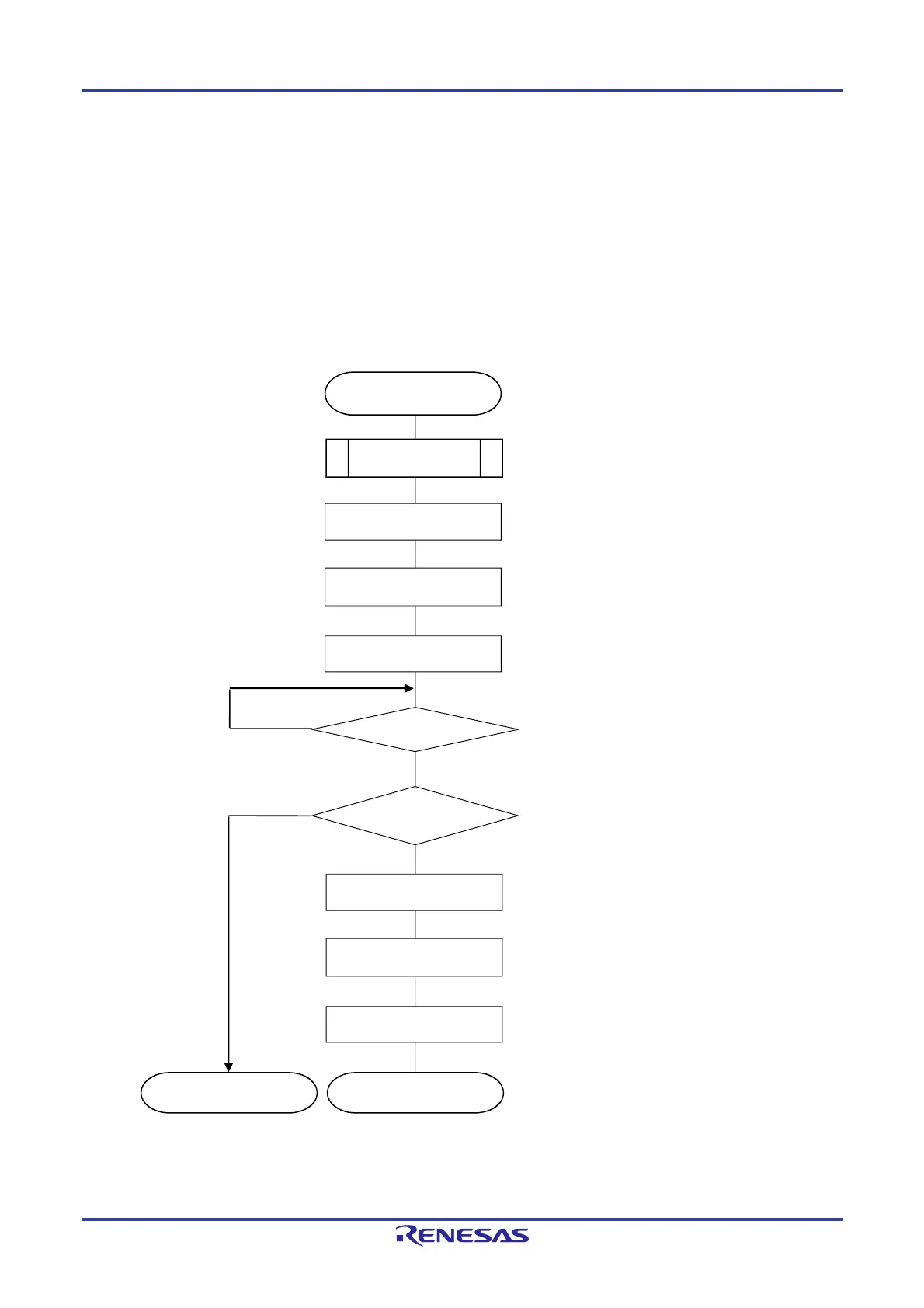
Figure 26-7. Processing Procedure After an Interrupt Is Generated
Perform re
uired save
rocessin
.
INTLVI generated
LVISEN = 1
Set the LVISEN bit to 1 to mask voltage detection
(LVIOMSK = 1).
LVISEN = 0
Set the LVISEN bit to 0 to enable voltage detection.
Save processing
Yes
No
LVD reset
generated
The MCU returns to normal operation when internal
reset by voltage detector (LVD) is not generated,
since a condition of V
DD becomes
V
DD VLVDH.
Set the LVILV bit to 0 to set the high-voltage detection
level (V
LVDH).
LVILV = 0
Normal operation
LVISEN = 1
Set the LVISEN bit to 1 to mask voltage detection
(LVIOMSK = 1)
LVISEN = 0
Set the LVISEN bit to 0 to enable voltage detection.
Set the LVIMD bit to 0 to set interru
t mode.
LVIMD = 0
Reset
No
Yes
LVIOMSK = 0
 Loading...


