12 Project Planning of Cooling System
12.1 Control Cabinet
12.1.1 Control Cabinet Design and Cooling
The only mounting position allowed for supply units and drive
controllers to be installed in control cabinets is G1.
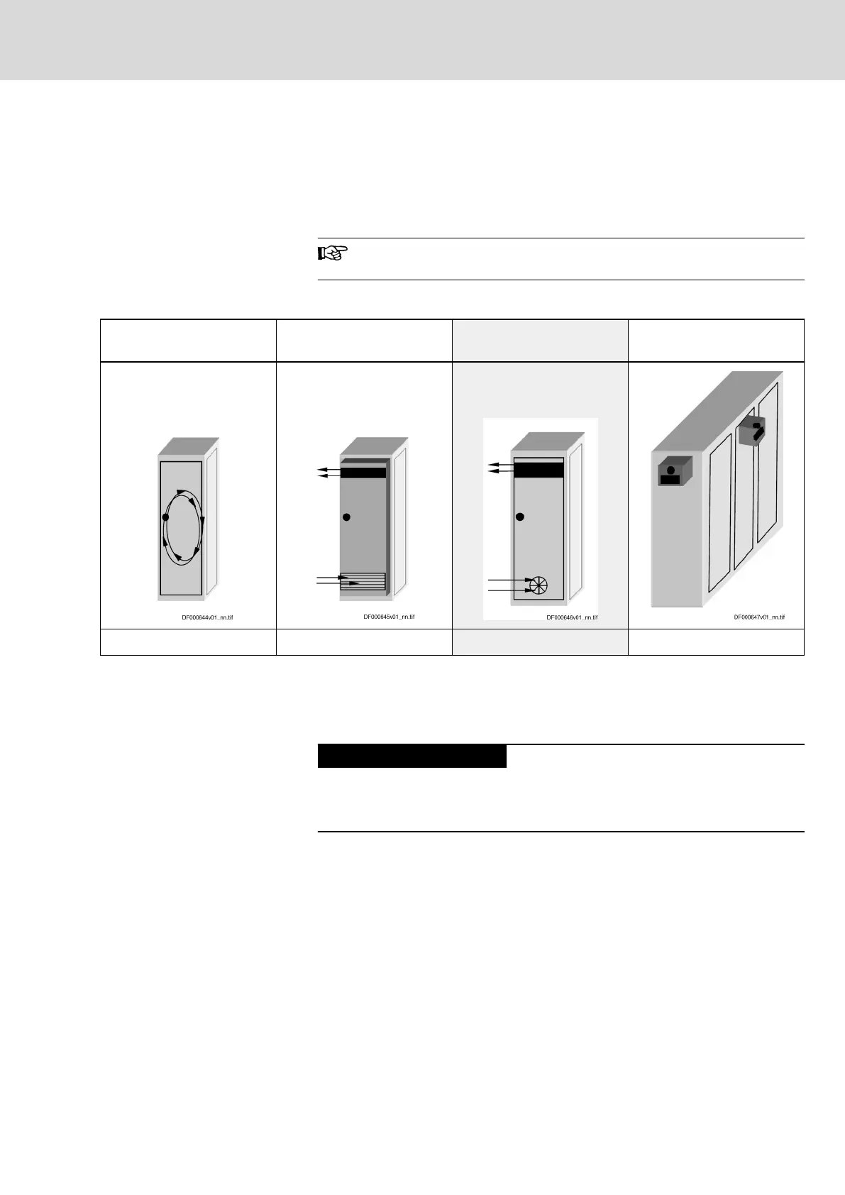
Possibilities of Heat Dissipation
Closed control cabinet with
air circulation
Closed control cabinet with
heat exchanger
Control cabinet with fan Closed control cabinet with
air conditioning unit
P
Q
~ 400 W P
Q
~ 1700 W P
Q
~ 2700 W P
Q
~ 4000 W
P
Q
Dissipated heat output
Tab.12-1: Possibilities of Heat Dissipation
The section below describes the "control cabinet with fan".
Requirements for Control Cabinets
with Fan
Risk of damage by unclean air in the control
cabinet!
Operating a control cabinet with a fan, but without the corresponding filters,
can damage the devices or cause malfunction.
● Install filters at the air intake opening of the control cabinet so that im‐
pure air cannot get into the control cabinet.
● Service the filters at regular intervals according to the dust loading in the
environment.
● Only replace the filters when the fan has been switched off, because
otherwise the fan sucks in the dirt coming off the filter and the dirt gets
into the control cabinet.
DOK-INDRV*-SYSTEM*****-PR06-EN-P
Rexroth IndraDrive Drive Systems with HMV01/02 HMS01/02, HMD01, HCS02/03
Bosch Rexroth AG 215/309
Project Planning of Cooling System