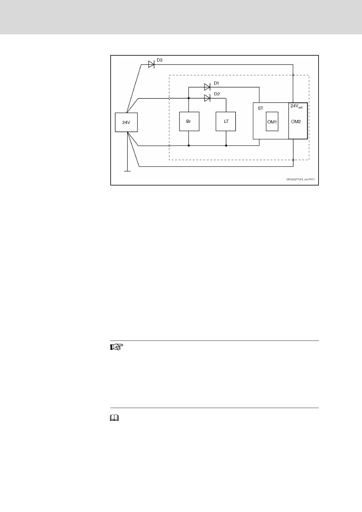
D1, D2 Diodes, internal
D3 Protective diode, external
LT Power section
BR Circuit motor holding brake
ST Control section
OM1 Optional modules
OM2 Optional modules with supply voltage connection, e.g. MA1, MD2
Fig.6-1: Block Diagram of 24V Supply
6.2.2 Electrical Requirements
The following parameters contain the essential electrical requirements on the
power supply unit:
● Output voltage or range of output voltage
● Continuous power which the power supply unit must supply during oper‐
ation
● Peak current which the power supply unit must supply when switching
on
Which Output Voltage Must the
Power Supply Unit Have?
The output voltage of the power supply unit must have been dimensioned
such that the voltage at the input of the devices ("24V supply": 24V; 0V) is
within the allowed voltage U
N3
.
Take into account that due to voltage drops, the output voltage of
the power supply unit is lower than the voltage at the devices.
Check the voltage at the input of the "24V supply" of the devices.
Use power supply units
● with adjustable output voltage from 24 V to 26 V
● which have been equipped with Sense inputs (this allows
compensating for the voltage drops on the line between
power supply unit and input "24V supply")
See Project Planning Manual "Rexroth IndraDrive Supply Units and Pow‐
er Sections" → Chapter of the respective device → "Technical Data" → "Basic
Data" → "Data for Control Voltage Supply".
Bosch Rexroth AG DOK-INDRV*-SYSTEM*****-PR06-EN-P
Rexroth IndraDrive Drive Systems with HMV01/02 HMS01/02, HMD01, HCS02/03
68/309
Project Planning of Control Voltage (24V Supply)