15.4 Other Calculations
15.4.1 Charging the DC Bus
To estimate the delay t
d
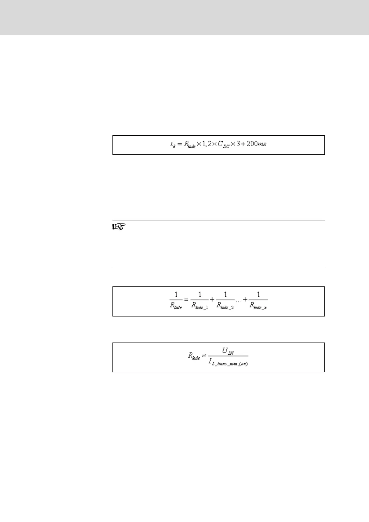
which a supply unit or a converter needs to charge
the DC bus, this applies:
Delay time t
d
is the time which passes from connection of mains voltage to
the device (from status "ready for operation") to status "drive ready".
(See also parameter "P-0-0115, Device control: status word" or "S-0-0135,
Drive status word")
Delay t
d
t
d
Delay
R
lade
Effective charging resistance
C
DC
Effective DC bus capacitance
200 ms Waiting time until charging process is completed
Fig.15-48: Delay for Three-Phase Operation
The interrelation applies to three-phase mains connection. For single-phase
mains operation, take the double time or control following processes via the
status "P-0-0115, Device control: status word".
Delay t
d
for HCS02
In HCS02 converters, the DC bus is charged via the integrated
braking resistor R
DC_Bleeder
.
The delay t
d
is approx. 2 seconds, independent of the DC bus ca‐
pacitance.
Effective Charging Resistance
with Several Mains Supplies
Effective charging resistance of all drive controllers at common DC bus con‐
nected to mains voltage:
Fig.15-49: Several Charging Resistances
Effective Charging Resistance
with One Mains Supply
Effective charging resistance of one drive controller at common DC bus con‐
nected to mains voltage:
U
LN
Applied mains voltage
I
L_trans_max_(o
n)
Inrush current at applied mains voltage
Fig.15-50: Charging Resistance
Bosch Rexroth AG DOK-INDRV*-SYSTEM*****-PR06-EN-P
Rexroth IndraDrive Drive Systems with HMV01/02 HMS01/02, HMD01, HCS02/03
276/309
Calculations