U
x
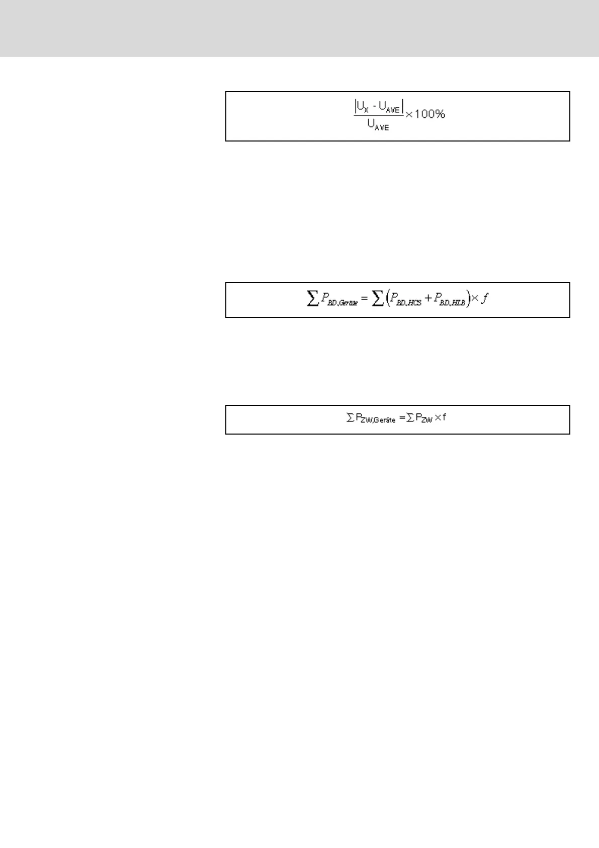
Phase-to-phase voltage with highest deviation from average value
U
AVE
= (U12 + U23 + U31) / 3; U12 , U23 , U31 being voltages between the
phases
Fig.15-37: Definition of Voltage Unbalance
15.2.5 Calculating the Allowed Continuous Power in the Common DC Bus
By interconnecting the DC bus connections of several HCS02 and HLB01
drive controllers, the regenerative power and continuous power generated in
the common DC bus are equally distributed to all IndraDrive C devices with
braking resistor.
Distribution to the involved devices takes place with high balancing factor.
For Central Supply and Group
Supply with DC Bus Connection
P
BD, Geräte
Braking resistor continuous power that all devices at common DC bus
can process in continuous operation, in kW
P
BD, HCS02
Braking resistor continuous power that the drive controller can proc‐
ess in continuous operation, in kW
P
BD, HLB01
Braking resistor continuous power that the additional braking resistor
module can process in continuous operation, in kW
f Balancing factor for parallel operation
Fig.15-38: Available Braking Resistor Continuous Power at Common DC bus
P
ZW, Geräte
Available DC bus continuous power at common DC bus, in kW
P
ZW
DC bus continuous power of the individual devices, in kW
f Balancing factor for parallel operation
Fig.15-39: Available DC Bus Continuous Power at Common DC Bus
DOK-INDRV*-SYSTEM*****-PR06-EN-P
Rexroth IndraDrive Drive Systems with HMV01/02 HMS01/02, HMD01, HCS02/03
Bosch Rexroth AG 263/309
Calculations