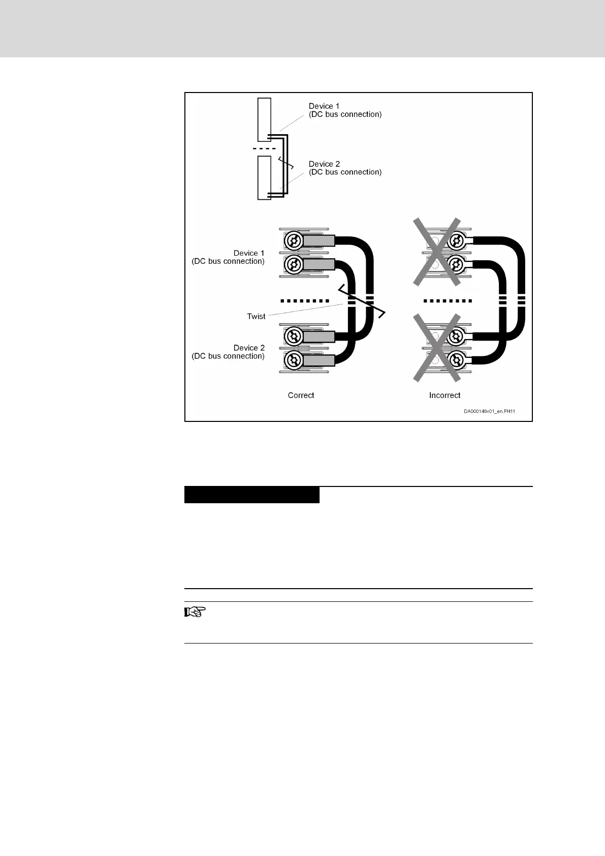
Fig.13-9: DC Bus Connections for Cable Routing to the Right
13.1.7 Connection of the Control Voltage Connections
General Information
Property damage in case of error caused by
too small line cross section!
Make use of the contact bars provided to loop-through.
Observe the current carrying capacity of the connections for 24V supply at
the devices used; see sections "Terminal Block, 24 - 0V (24V Supply)" and
"X13, Control Voltage" in the "Project Planning Manual "Rexroth IndraDrive
Supply Units and Power Sections"".
Connect the connections X13 of components with connector for
24V supply individually and in star-shaped form to the 24V supply
in the control cabinet.
Bosch Rexroth AG DOK-INDRV*-SYSTEM*****-PR06-EN-P
Rexroth IndraDrive Drive Systems with HMV01/02 HMS01/02, HMD01, HCS02/03
232/309
Connections of the Components in the Drive System