Technical Data of the Connection Point
View Identifica‐
tion
Function
+24V Power supply
Connection to neighboring devices with contact bars from
accessory HAS01.1
0V Reference potential for power supply
Connection to neighboring devices with contact bars from
accessory HAS01.1
Screw connection
M6 thread at device (terminal block)
Unit Min. Max.
Tightening torque Nm 5,5 6,5
Power consumption W P
N3
(see technical data)
Voltage load capacity V U
N3
(see technical data)
Polarity reversal protection Within the allowed voltage range by internal protective diode
Current carrying capacity "looping through" from 24V to 24V, 0V to 0V
(contact bars in scope of supply of accessory HAS01)
With contact bars -072 A 220
Tab.13-5: Function, Pin Assignment, Properties
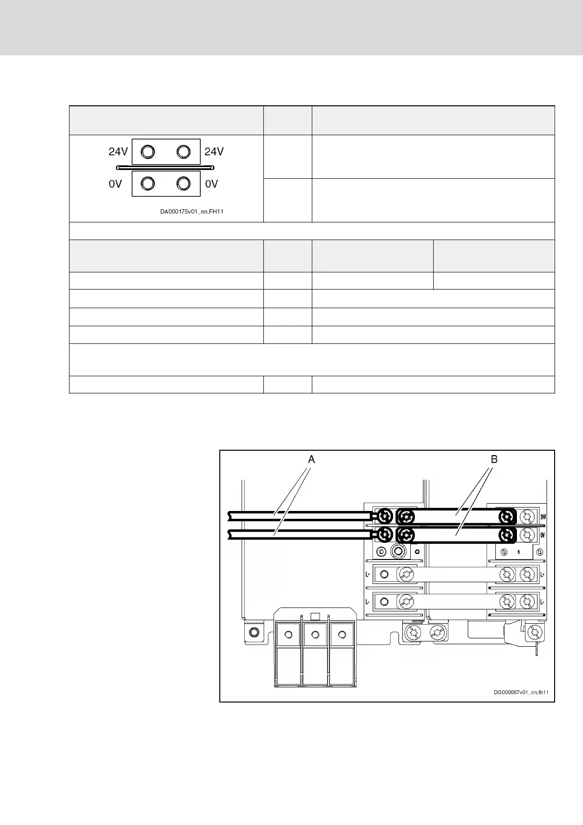
Single-Line Arrangement
The figure below illustrates the connection point and connection of the control
voltage connections for devices HMV01, HMV02, HMS01, HMS02, HMD01
HLB01.1D and HCS03 in single-line arrangement.
A Cable (to source of control voltage supply)
B Contact bars
Fig.13-10: Connection Points and Connections of Control Voltage
DOK-INDRV*-SYSTEM*****-PR06-EN-P
Rexroth IndraDrive Drive Systems with HMV01/02 HMS01/02, HMD01, HCS02/03
Bosch Rexroth AG 233/309
Connections of the Components in the Drive System