13.1.6 Connection of the DC Bus Connections
General Information
Property damage in case of error caused by
too small line cross section!
Observe the current carrying capacity of the connection lines at the DC bus
connections of the components used; see chapter "DC Bus Connection (L+,
L-)" in the Project Planning Manual "Rexroth IndraDrive Supply Units and
Power Sections".
Install connection lines at the DC bus connections in such a way that they are
protected by the line protection at the mains connection of the supply unit or
by additional fuses before the connection line.
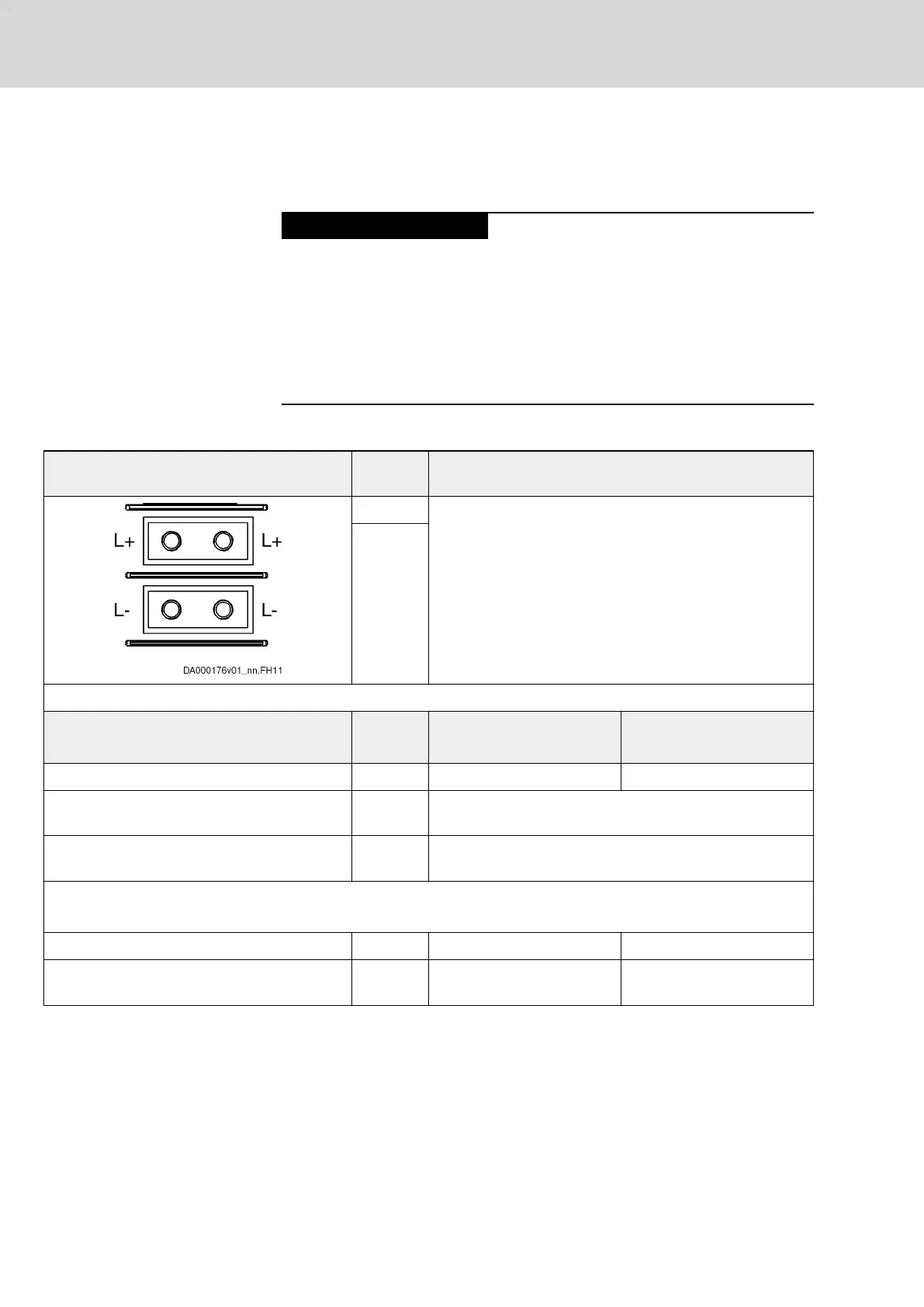
Technical Data of the Connection Point
View Identifica‐
tion
Function
L+ Connection points for connecting DC bus connections
L-
Screw connection
M6 thread at device (terminal block)
Unit Min. Max.
Tightening torque Nm 5,5 6,5
Short circuit protection Via fusing elements connected in the incoming circuit to the
mains connection
Overload protection Via fusing elements connected in the incoming circuit to the
mains connection
Current carrying capacity "looping through" from L+ to L+, L- to L-
(contact bars in scope of supply of accessory HAS01)
With contact bars -072 A 220
Additionally with contact bars ‑042 and end
piece
A 245
Tab.13-3: Function, Pin Assignment, Properties
Single-Line Arrangement
The figure below illustrates the connection point and connection of the DC
bus connections in the case of single-line arrangement with contact bars for
the system components
● HMV01
● HMS01
● HMD01
Bosch Rexroth AG DOK-INDRV*-SYSTEM*****-PR06-EN-P
Rexroth IndraDrive Drive Systems with HMV01/02 HMS01/02, HMD01, HCS02/03
228/309
Connections of the Components in the Drive System