P
BD_1
,
P
BD_2
, P
BD_n
Data sheet data of the braking resistors
f Balancing factor for PDB (f = 0.8 (guide value); see also technical data
of converter and supply unit)
Fig.15-25: Sum of Braking Resistor Continuous Powers
Relative Duty Cycle of Braking Re‐
sistor
The quotient of t
on
and T
cycl
is understood by the duty cycle ED. The maxi‐
mum allowed relative duty cycle ED
max
is calculated from the nominal data for
HLR braking resistors:
ED
max
Maximum allowed relative duty cycle
t
on
Allowed duty cycle
T
cycl
Allowed cycle time
Fig.15-26: Relative Duty Cycle of Braking Resistor
Braking times
Within the indicated minimum cycle time T
cycl
, the braking resistor
may be switched on, as a maximum, for the time t
on
.
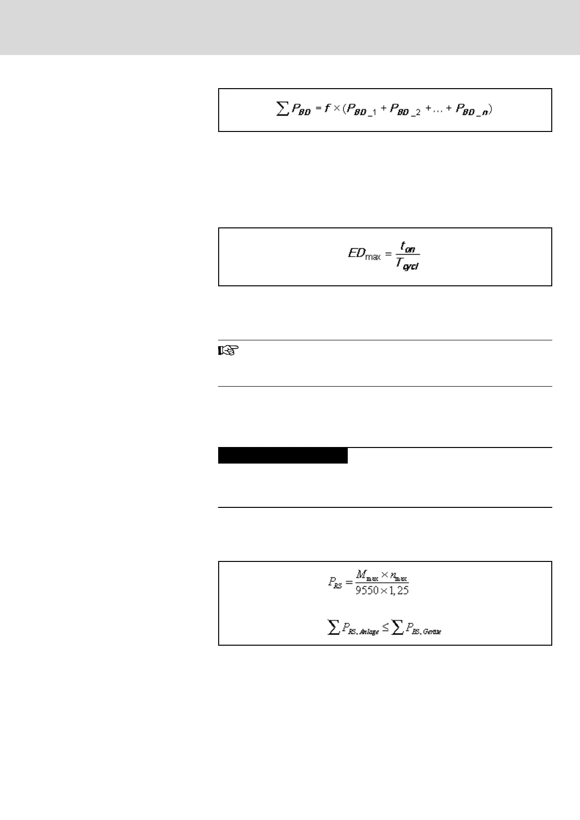
15.1.7 Peak Regenerative Power
Usually, peak regenerative power will occur when an E-Stop signal is trig‐
gered and all axes brake simultaneously.
Risk of damage due to extended braking
times and distances!
Select the supply unit such that the sum of peak regenerative powers of all
drives does not exceed braking resistor peak power of the supply unit.
See the respective motor selection data for the peak regenerative powers.
Peak regenerative power can be roughly calculated by the following equa‐
tion:
P
RS,Anlage
Generated peak regenerated power [kW]
P
BS,Geräte
Allowed braking resistor peak power [kW]
M
max
Maximum drive torque [Nm]
n
max
Maximum NC useful speed [min-1]
1,25 Constant for motor and controller efficiency
Fig.15-27: Peak Regenerative Power
DOK-INDRV*-SYSTEM*****-PR06-EN-P
Rexroth IndraDrive Drive Systems with HMV01/02 HMS01/02, HMD01, HCS02/03
Bosch Rexroth AG 257/309
Calculations