Peak Power of Braking Resistor
The braking resistor makes available the peak power during its duty cycle.
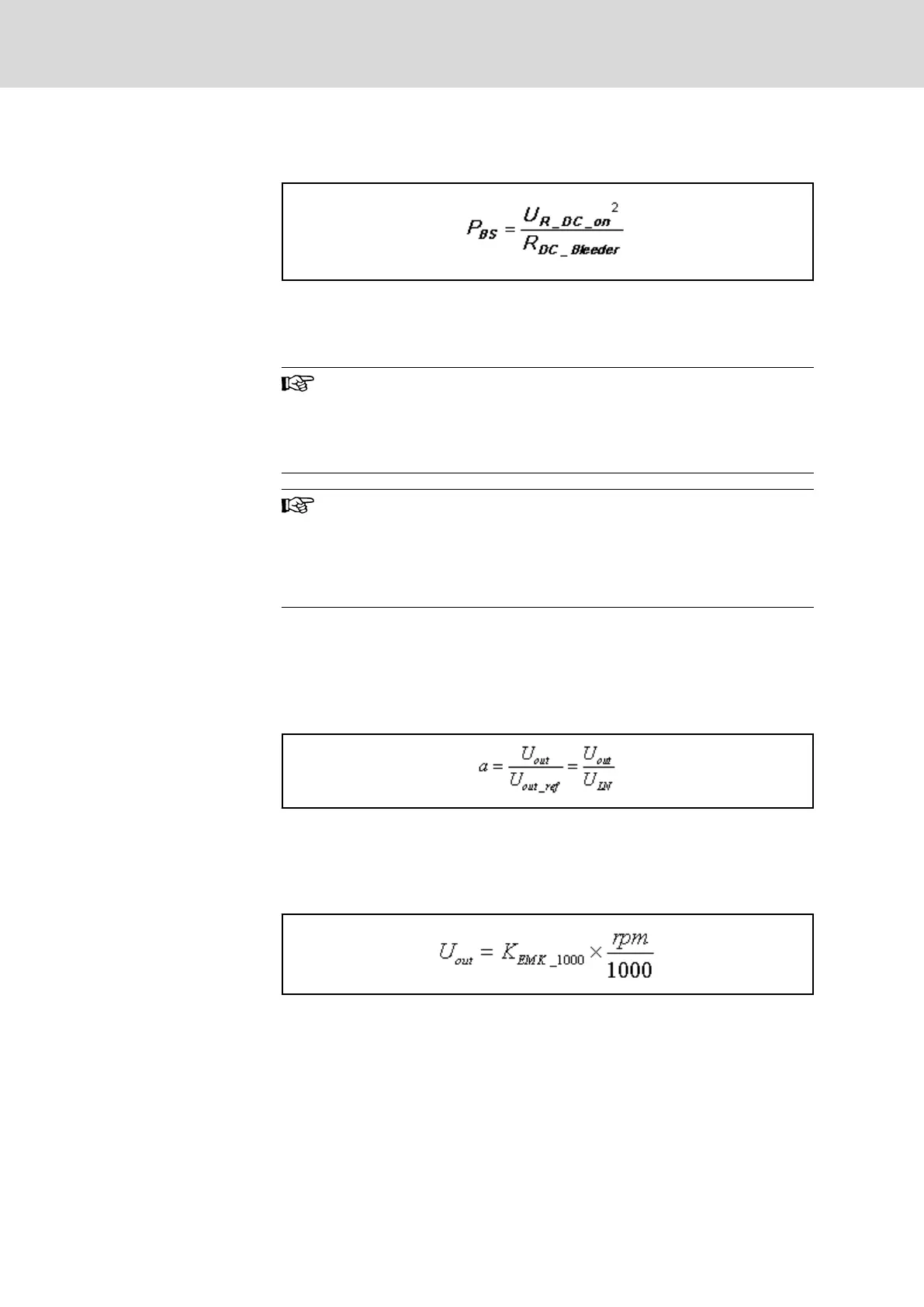
The peak power is calculated as follows:
P
BS
Effective peak power
U
R_DC_on
Switch-on threshold
R
DC_Bleeder
Fig.15-28: Braking Resistor Peak Power
Several braking resistors (e.g. HLR) at common DC bus
With several braking resistors at the DC bus, the available peak
power is determined as the sum of the individual peak powers.
For this purpose, the same switch-on threshold must take effect
for all involved braking resistors.
Adjustment of switch-on threshold!
For the adjustment of the switch-on threshold, see also the follow‐
ing parameters:
● P-0-0833, Braking resistor threshold
● P-0-0858, Data of external braking resistor
15.1.8 Calculating the Control Factor
The control factor of an inverter is the ratio of its output voltage to a reference
output voltage.
The reference output voltage is the output voltage of the inverter at mains in‐
put voltage without overload.
U
out
Output voltage of inverter
U
out_ref
Reference output voltage
U
LN
Mains voltage
Fig.15-29: Control Factor
Calculating U
out
:
U
out
Output voltage of inverter
K
EMK_1000
Voltage constant [V/min
-1
]
rpm Speed
Fig.15-30:
If several inverters have effect on one supply unit at the same time, you have
to consider the so-called mean control factor scaled with the axis power.
Bosch Rexroth AG DOK-INDRV*-SYSTEM*****-PR06-EN-P
Rexroth IndraDrive Drive Systems with HMV01/02 HMS01/02, HMD01, HCS02/03
258/309
Calculations