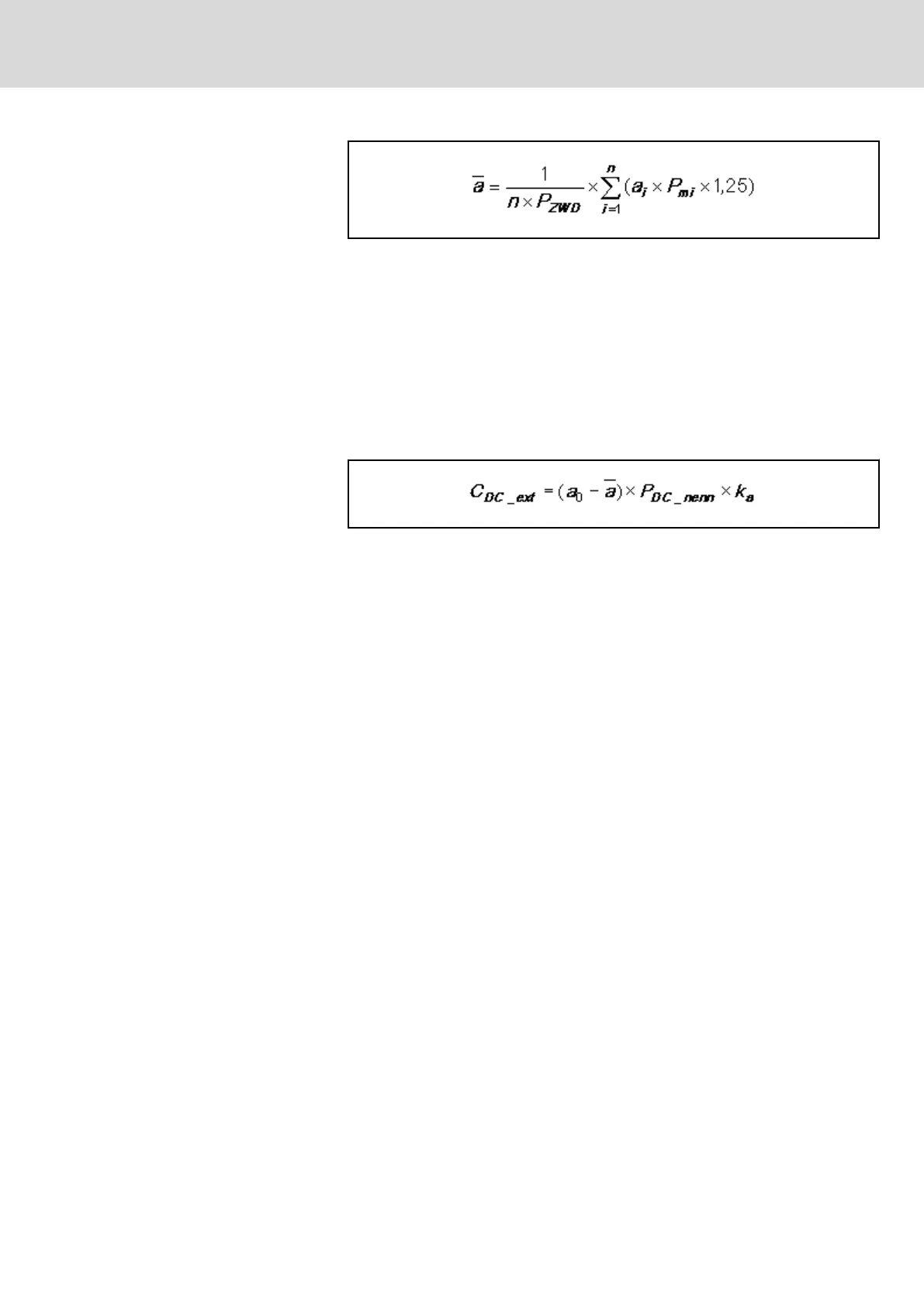
n Number of inverters
a
i
Several control factors
P
ZWD
DC bus continuous power [kW]
P
mi
Mechanical continuous power [kW]
Fig.15-31: Mean, Scaled Control Factor
When the control factor falls below the given value (see data P
DC_cont
in the
technical data of the corresponding supply unit), additional wattless power
occurs. The additional wattless power can be compensated with additional
capacitors in the DC bus. The required additional capacitance can be approx‐
imately calculated with the following formula.
Applies to a ≤ a
0
!
C
DC_ext
Required additional capacitance in DC bus in μF
a
0
Minimum required control factor
a Calculated mean control factor
P
DC_nenn
Nominal power of supply unit [kW]
k
a
200 (preliminary); factor capacitance [μF] / nominal power [kW]
Fig.15-32: Required Additional Capacitances When Control Factor Falls Below
Minimum Value
DOK-INDRV*-SYSTEM*****-PR06-EN-P
Rexroth IndraDrive Drive Systems with HMV01/02 HMS01/02, HMD01, HCS02/03
Bosch Rexroth AG 259/309
Calculations