● Both values (voltage change, peak voltage) are influenced by:
– DC bus voltage:
The higher the DC bus voltage at which the drive system is operat‐
ed, the higher the value of the voltage change and the occurring
peak voltage.
– Length and electrical properties of the motor cable:
The shorter the motor cable, the less the attenuation effects.
The longer the motor cable, the higher the degree of voltage over‐
shoot at the motor-side cable end.
– For a motor cable length l < 25 m and mains voltage
U
N3
> AC 440 V, it is recommended that you use voltage-reducing
components.
Apart from the nominal current I
N
, especially take the maximum
allowed switching frequency of the power output stage (f
s
) into ac‐
count with which the motor filter HMF may be operated.
Verify the success of the voltage-reducing measures.
14.2.3 Minimum Inductance of Third-Party Motor
Depending on the drive controller used, the motor has to have a minimum
value for inductance. The actually available inductance of a motor can be
measured directly between two motor terminals by means of an inductance
measuring bridge. The measurement has to be made for a complete motor
wired for normal operation but not yet connected. During the measurement,
one motor terminal remains open! For asynchronous motors, the measured
value can only be used if the rotor doesn't have closed slots!
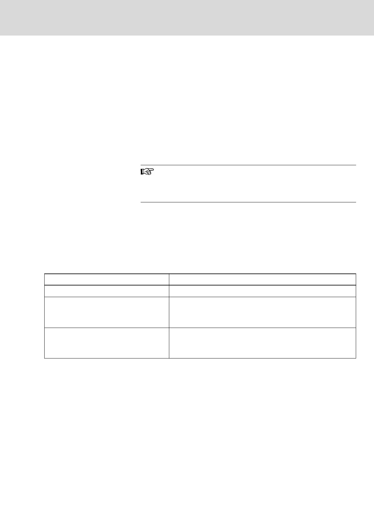
Drive controller Minimum required motor inductance
HCS at 3 × AC 230 V L
U-V
= 60 × 4 / (√2 × I
Typ
× f
s
) (in mH)
HMS, HMD at HMV (3 × AC 400 V)
HMS, HMD at HCS (3 × AC 400 V)
HCS at 3 × AC 400 V
L
U-V
= 80 × 4 / (√2 × I
Typ
× f
s
) (in mH)
HMS, HMD at HMV (3 × AC 480 V)
HMS, HMD at HCS (3 × AC 480 V)
HCS at 3 × AC 480 V
L
U-V
= 116 × 4 / (√2 × I
Typ
× f
s
) (in mH)
I
Typ
Maximum current of drive controller according to type code (rms val‐
ue)
f
s
Desired switching frequency in kHz
Tab.14-1: Minimum Inductances Depending on Drive Controller Data, Supply
Units and Supply Voltage
Install a three-phase choke in the motor feed wire, if the inductance of the
third-party motor is smaller than indicated in the table above. This choke has
to increase the inductance that can be measured between two motor termi‐
nals to the minimum value.
DOK-INDRV*-SYSTEM*****-PR06-EN-P
Rexroth IndraDrive Drive Systems with HMV01/02 HMS01/02, HMD01, HCS02/03
Bosch Rexroth AG 243/309
Third-Party Motors at Rexroth IndraDrive Controllers