Process Control and MUSIC
571
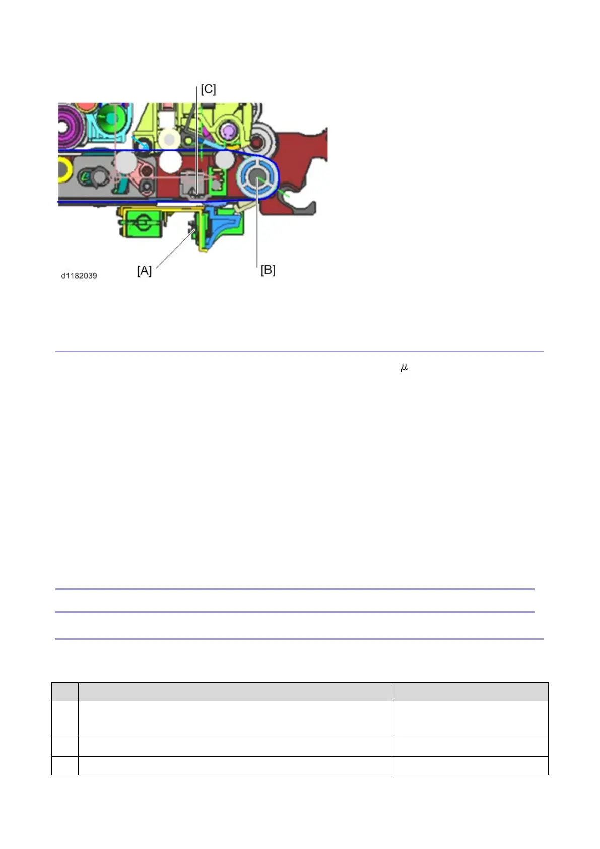
The ID sensors [A] are installed at the upstream side of the paper transfer roller [B] and detect image density at
the plate [C]. This layout allows the machine to detect a pattern faster and to help reduce waiting time.
TD Sensor
In this model, a non-contact toner density (TD) sensor, which we also call a mu ( ) sensor, is used for toner
density control.
The TD sensor is attached on the lower side of the development unit. Unlike a HST sensor, the board of the TD
sensor is exposed. So there is a cover around the sensor to protect it and to maintain a good contact between the
sensor and development unit.
The TD sensor measures the permeability of the developer without contacting it, from the outside of the case,
and converts the measured value to the toner density.
According to the toner density measured by this sensor, the proper amount of toner is supplied to the developer.
A counter corresponding to the frequency is used as the unit of TD sensor output. Thus, unlike a HST sensor
which directly detects Vt, the TD sensor output is converted into Vt for toner supply control.
In the TD sensor, there is an ID chip storing the machine identification information, the running distance
information of Development unit and PCU, and other information used by image density control.
MUSIC
Color Skew Adjustment Timing
This model has a mechanism that adjusts color skew, which we call MUSIC. The machine creates a pattern for
correction, measures the image position by the pattern, and adjusts the image position.
No. MUSIC performs when: Notes
1 The power switch is just turned on, or the machine recovers from the
energy save mode.
Executes [Mode b] (*2) or [Mode
a] (*1)
2 The machine does a print job. Executes [Mode b] (*2)
3 Printing is completed. Executes [Mode b] (*2)