8. PARAMETER DESCRIPTION
IMR02C15-E4
8-46
Continued from the previous page.
Continued on the next page.
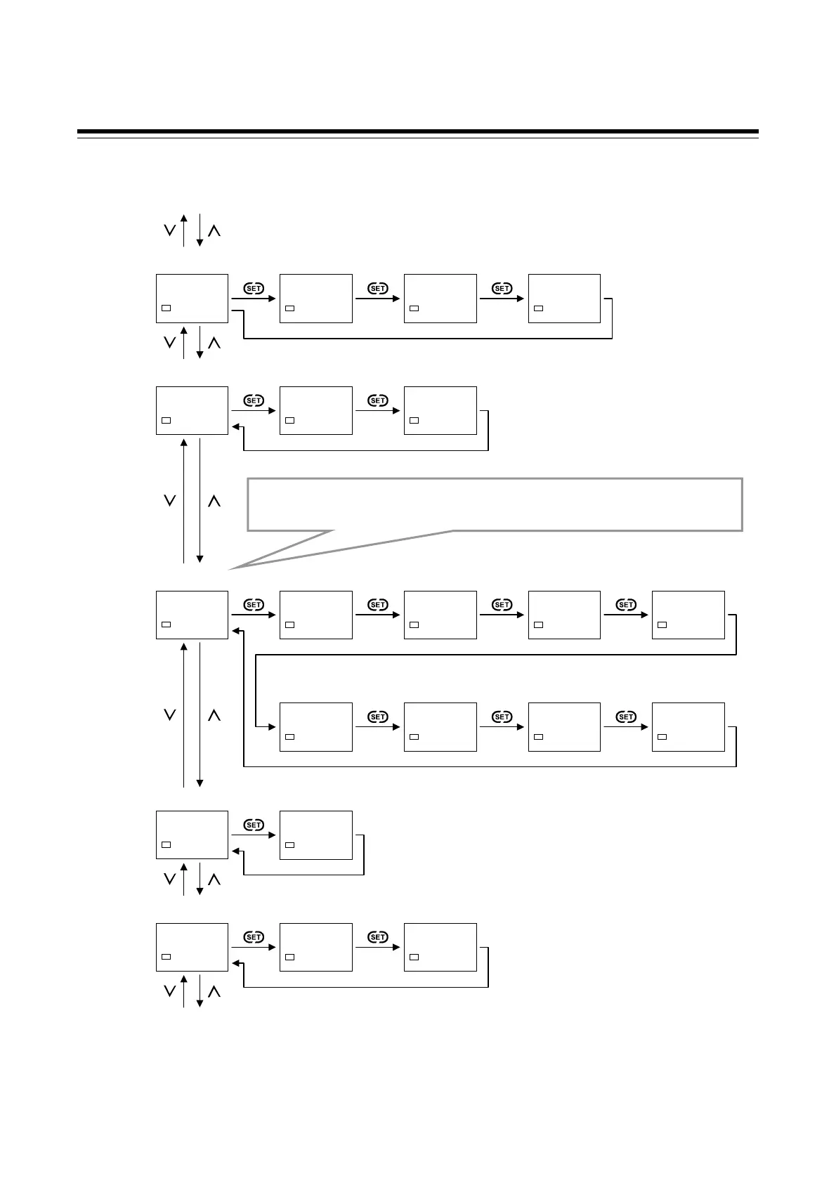
Function block 08 (F08)
Function block 09
(F09)
F09.
SV1
(P. 8-84)
PB$
0000
SV1
PV bias
DF
0001
SV1
PV digital filter
S.F09
0000
SV1
F09 block selection
(no display)
(P. 8-84) (P. 8-84) (P. 8-85)
Function block 10
(F10)
F10.
SV1
(P. 8-86)
M-MV%
000.0
SV1
Manual manipulated
output value (MV)
S.F10
0001
SV1
F10 block selection
(no display)
(P. 8-86) (P. 8-87)
Function block 21
(F21)
F21.
SV1
(P. 8-88)
INP
0002
SV1
Input type
PGDP
0000
SV1
Decimal point
position
BOS
0000
SV1
Burnout direction
PGSH$
1372
SV1
Input scale high
(P. 8-88) (P. 8-90) (P. 8-90) (P. 8-91)
PGSL$
-200
SV1
Input scale low
(P. 8-91)
Function block 23
(F23)
F23.
SV1
(P. 8-95)
DISL
0000
SV1
DI assignment
(P. 8-95)
Function block 33 (F33)
Prior to change in values of parameters in the blocks from F21 to F91, unlock and STOP
(control stop) the instrument. To display parameters in the blocks from F21 to F91, set
“128” to the mode selection at F00.
SLH$
1372
SV1
Setting limiter high
(P. 8-93)
SLL$
-200
SV1
Setting limiter low
(P. 8-93)
DSOP
0000
SV1
PV flashing display
at input error
(P. 8-94)
Function block 30
(F30)
F30.
SV1
(P. 8-96)
SS
0000
SV1
Output action at
STOP mode
(P. 8-96)
SPCH
0001
SV1
STOP display
selection
(P. 8-97)

 Loading...


