118 Rockwell Automation Publication 2198-UM001M-EN-P - November 2022
Chapter 6 Configure and Start the Kinetix 5500 Drive System
12. From the pull-down menus, choose the power options appropriate for
your actual hardware configuration.
13. Click OK.
14. Repeat step 1
through step 13 for each 2198-Hxxx-ERSx servo drive.
IMPORTANT The Logix Designer application enforces shared-bus configuration
rules for Kinetix 5500 drives, except for shared AC configurations.
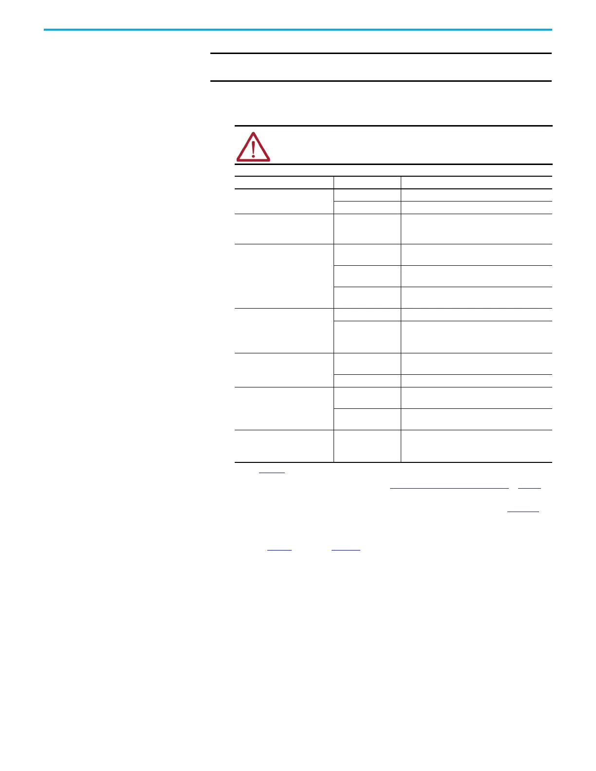
ATTENTION: To avoid damage to equipment, make sure the AC input
voltage that is configured in the Logix Designer application matches
the actual hardware being configured.
Attribute Menu Description
Voltage
400-480 VAC 324…528 AC rms input voltage
200-240 VAC 195…264 AC rms input voltage
AC Input Phasing
• Three Phase
• Single Phase
Input power phasing. Kinetix 5500 drives with
single-phase operation is limited to 2198-H003-
ERSx, 2198-H008-ERSx, and 2198-H015-ERSx.
Bus Configuration
(1)
(2)
(1) See Chapter 3 for more information on single-axis and multi-axis configurations.
(2) Bus Configuration selection is not applicable to all EtherNet/IP drives.
Standalone
Applies to single-axis drives and drives with
Shared AC input configurations.
Shared AC/DC
Applies to converter drives with Shared AC/DC
and Shared AC/DC Hybrid input configurations.
Shared DC
Applies to inverter drives with Shared DC input
(common-bus) configurations.
Bus Sharing Group
(3)
(2)
(3) For more information on bus-sharing groups, refer to Understand Bus-sharing Group Configuration on page 133.
Standalone Applies to standalone bus configurations.
•Group1
•Group2
•Group3…
Applies to any bus-sharing configuration.
(4)
(4) All drives physically connected to the same shared-bus connection system must be part of the same Bus Sharing
Group in the Logix Designer application.
Shunt Regulator Action
Disabled
Disables the internal shunt resistor and external
shunt option.
Shunt Regulator Enables the internal and external shunt options.
Shunt Regulator Resistor Type
Internal
Enables the internal shunt (external shunt option
is disabled).
External
Enables the external shunt (internal shunt option
is disabled).
External Shunt
(5)
(5) See the Kinetix 5700, 5500, 5300, and 5100 Servo Drives Specifications Technical Data, publication KNX-TD003, for
more information on the Bulletin 2097 external shunt resistors.
•None
•2097-R6
•2097-R7
Selects external shunt option. Only the shunt
model that is intended for the drive model is
shown.

 Loading...


