Publication 1734-UM001D-EN-P - April 2008
198 Configure POINT I/O Modules in RSLogix 5000 Software
2. From the Configuration dialog, complete entries, referring to the table.
3. From the bottom of the Configuration dialog, perform one of the
following:
• Click another tab at the top of the dialog.
or
• Click OK to save changes and close the dialog.
or
• Click Cancel to return to default values.
or
• Click Apply to save changes you made on any of the dialogs and
continue to display the dialog, noting that you enable the Apply
button when you make changes to any of the dialogs.
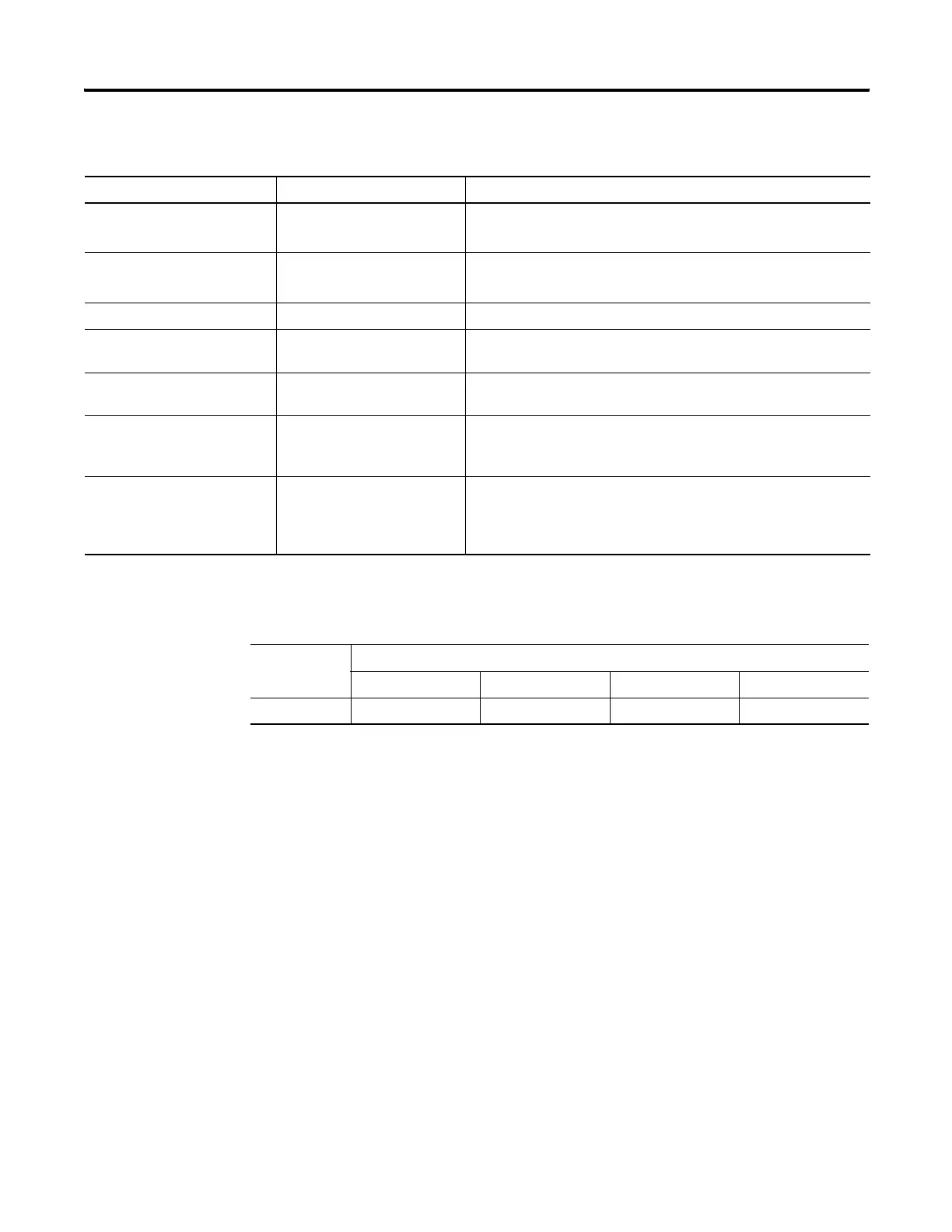
For This Value Select Comments
High Engineering -32768…32767 • Default for 1734-IE2C analog input module is 16383.
• Default for 1734-IE2V analog input module is 10000.
Low Engineering -32768…32767 • Default for 1734-IE2C analog input module is 3277.
• Default for 1734-IE2V analog input module is 0.
Digital Filter (ms) 0…10000 Default is 0.
Current Range 4…0 mA
0…20 mA
Default is 4…20 mA.
Voltage Range -10…10V
0…10V
Default is 0…10V
Real Time Sample (ms) 0…10000 Default is 100.
Refer to the Real Time Sample Values table for the relationship
between Notch Filter and Real Time Sample.
Notch Filter 50 Hz
60 Hz
250 Hz
500 Hz
Default is 60 Hz.
Refer to the Real Time Sample Values table for the relationship
between Notch Filter and Real Time Sample.
Real Time Sample Values
Real Time
Sample
Notch Filter Setting
50 Hz 60 Hz 250 Hz 500 Hz
Min 120 ms 100 ms 24 ms 12 ms
 Loading...