DescriptionSourceGroup
The same source as is
active on the program bus of
the selected ME.
ME X PGMME Bus
Follows
The same source as is
active on the preview bus of
the selected ME.
ME X PST
The video, or fill, of the
same source as is active on
the selected key bus of the
selected ME.
ME X KEYY
The alpha of the same
source as is active on the
selected key bus of the
selected ME.
ME X
KEYYAlpha
The same source as is
active on the selected utility
bus.
ME X
UTIL1/2
The output of the input
MultiViewer for the video
input board in the selected
slot.
MV InXInput
MultiViewers
The output of the extra input
21 on the Evertz
®
IP Input
board. The input source is
routed directly to the output.
X21Extended
Inputs
These items are fixed to the
outputs of the AuxKey
assigned to the selected
output BNCs.
(fixed)Aux Mix
Outputs
These items are fixed to the
outputs of the Mix/DSK
option.
(fixed)Mix/DSK
Output
The output of each DVE
channel resource from the
Floating 3D DVE.
MVX DVEYMultiViewer
3D DVE
4. Use the Color Gamut buttons to set the color
gamut conversion you want to apply to the output.
Note: There are restrictions on the types of HDR and color
gamut conversion you can do, and you can adjust the
scaling of the conversion. Refer to High Dynamic Range
(HDR) and Wide Color Gamut (WCG) Conversion on page
83 for more information.
• BT.709 — color gamut recommended for HD
video signals.
• BT.2020 — wide color gamut recommended for
UHDTV1 video signals.
5. Use the Dynamic Range buttons to set the
dynamic range conversion you want to apply to the
output.
• SDR — Standard Dynamic Range.
• HLG — Hybrid Log Gamma.
• PQ — Perceptual Quantizer.
• S-Log3 — Sony
®
S-Log3.
6. Press HOME > Confirm.
To Confirm a Video Output
The Aux Bus Outputs (2-2) menu lists all video outputs
on the switcher and the video source that is assigned to
each. The Aux Bus Outputs (1-2) menu lists the video
source selected on each aux bus.
1. Press HOME > More > Effects > More > More
> More > Aux Bus > More.
2. Press Output X##-X## for the Video Output board
(X) and output BNC range (##) that you want to
conrm the video outputs for.
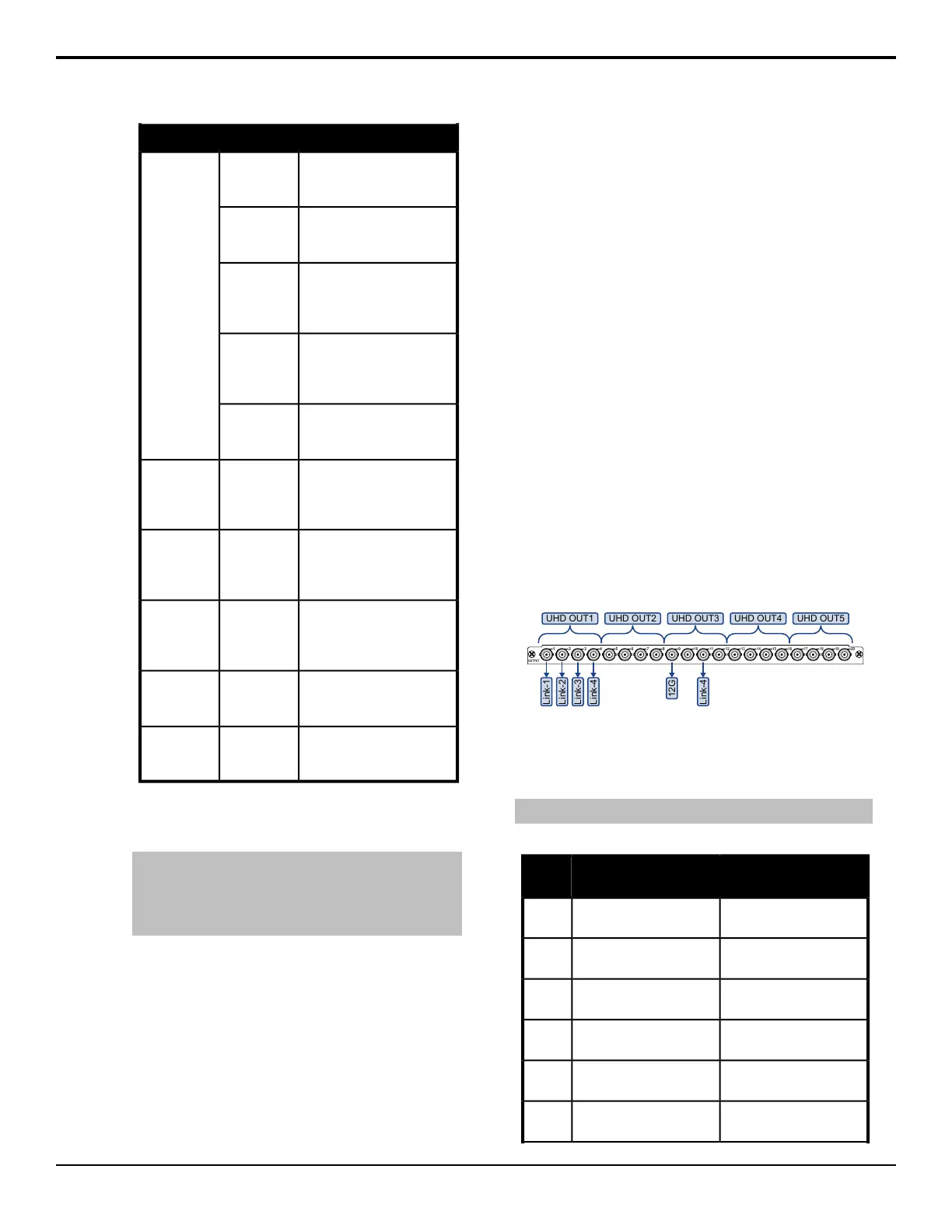
UHDTV1 Video Output
The switcher must be congured to output UHDTV1 at
12Gb/s. Output BNCs are assigned to a UHDTV1 output
in groups of four (4). If you want to output UHDTV1 at
12Gb/s, you must set the output group to 12G. If you
want to output UHDTV1 in UHD-2SI at 3Gb/s, the
switcher will automatically output the four sub images
to the four output BNC in the output group.
OUTPUT
1 2 3 4 5 6 7 8 9
10 11 12 13 14 15 16 17 18 19 20
UHD OUT5UHD OUT1 UHD OUT2 UHD OUT3 UHD OUT4
Link-1
Link-2
Link-3
Link-4
12G
Link-4
When the output group is set to 12Gb/s, the rst BNC
in the group outputs the 12Gb/s UHDTV1 stream and
the third BNC outputs one of the sub images (links) at
3Gb/s as a camera return.
Note: Only the 12G Output can output UHDTV1 at 12Gb/s video.
Table 5: UHDTV1 Output BNC Assignments
UHD-2SI 12Gb/sUHD-2SI 3Gb/sOutput
BNC
Group 1 - ImageGroup 1 - Sub Image 1
(image at quarter scale)
1
--Group 1 - Sub Image 2
(image at quarter scale)
2
Group 1 - 3G Camera
Return (Link 3)
Group 1 - Sub Image 3
(image at quarter scale)
3
--Group 1 - Sub Image 4
(image at quarter scale)
4
Group 2 - ImageGroup 2 - Sub Image 1
(image at quarter scale)
5
--Group 2 - Sub Image 2
(image at quarter scale)
6
32 • Video Output Setup — Acuity Setup Manual (v9.2)
 Loading...


