module. Only the source button modules have this
knob.
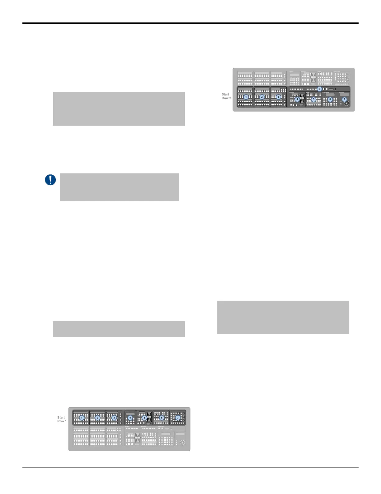
Each source button module on the control panel has
8 buttons, so the rst button on module 1 is 1, the
rst button on module 2 is 9, and so on.
Tip: If you are assigning a module with custom control
buttons, press Custctrl & GPI Group and use the First
Custctrl knob to select the number, or position, of the first
custom control button on the module. This is usually the
same as the First Crosspoint selection.
7. Press HOME > Confirm.
To Automatically Map Modules to a Row
Modules are mapped to rows so that the system can
identify where the hardware is located on the panel.
Important: Do not manually map SideShotNet,
SideSlideNet, or SideStick modules to the panel.
Panel mapping for these modules is done from the
communications menu when you set them up.
1. Press HOME > Setup > More > Panel Modules.
2. Press Yes.
3. Press Quick Configuration.
4. Select whether you want to assign modules to an
internal panel row (Internal Rows), or an external
panel row (External Rows).
• Internal Rows — rows inside the control panel,
or connected to the touchscreen display.
• External Rows — rows outside the control
panel, such as on an auxiliary control panel,
SideBox, not including the touchscreen display.
5. Press the Start Row X button for the row that you
want to start assigning modules to.
Note: Any module assignments to the selected row are
lost.
6. Press a button on all the modules that you want to
assign to the selected row starting with the rst
source button/crosspoint module on the left.
Remember to include memory and transition
modules as well.
The order that source button modules are assigned
to a row sets the order that the switcher maps to the
buttons.
BANK STOP ATTACH
PAUSE RECORD DELETE
RECALL
BANK ENTER
KEYS
ONLY
EFF
DISS
STORE
ME
RATE
KEY
RATE
MEMORY
RECALL STORE
7 8 9
4 5 6
1 2 3
0
EFF
RATE
ATTRIB
7 8 9
4 5 6
1 2 3
RUNCC
+/-
0
.
BANK CLEAR
ENTER
ME
2
ALL
ME
1
RECALL
CLIP/CC
ALL
ME
4
ME
3
ME
1
ME
2
ME
4
ME
3
FADE
RATE
+4
ME
RATE
EFF
RATE
KEY
RATE
UNDO
ATTRIB
KEYS
ONLY
EFF
DISS
GLOBAL MEMORY
RECALL STORE
CUT CUT CUT CUT CUT CUT CUT CUT
MASK
SEL SEL SEL SEL SEL SEL SEL SEL
SELF
KEY
AUTO
SELECT
CHROMA
KEY
PST
PATT
MATTE
FILL
KEY
MEM
KEY
INV
2D
DVE
3D
DVE
BORDER
CHNL
MGMT
SHOW
ALPHA
KEY
PV
KEYERS
1 2 3 4 5 6 7 8
AUTO
TRANS
AUTO
TRANS
AUTO
TRANS
AUTO
TRANS
AUTO
TRANS
AUTO
TRANS
AUTO
TRANS
AUTO
TRANS
CUT CUT CUT CUT CUT CUT CUT CUT
MASK
SEL SEL SEL SEL SEL SEL SEL SEL
SELF
KEY
AUTO
SELECT
CHROMA
KEY
PST
PATT
MATTE
FILL
KEY
MEM
KEY
INV
2D
DVE
3D
DVE
BORDER
CHNL
MGMT
SHOW
ALPHA
KEY
PV
KEYERS
1 2 3 4 5 6 7 8
AUTO
TRANS
AUTO
TRANS
AUTO
TRANS
AUTO
TRANS
AUTO
TRANS
AUTO
TRANS
AUTO
TRANS
AUTO
TRANS
HOME
UP
ONE
HOLD
TOP
MENU
MENU KEYPAD
PGMSRC PVME4 +4ME 3ME2ME 1
PREVIEW
SAFE
TEXT
HIDE
OVLY
MASK
PV
TIME
CLOCK
CENTER
SAFE
TITLE
VTR
TC
SOURCE
ID
MONITORING
CUT FADE
FADE TO BLACK
FRAMES
USB
KEY5 KEY6 KEY7
PGM
A
PGM
B
PST
BKGD
KEY
PRIOR
DISS WIPE DVE SEQ
KEY8
BKGD
KEY1 KEY2 KEY3 KEY4
TRANS
LIMIT
MEDIA
ROLL
CLIP
TRANSITION
FRAMES
CUT
AUTO
TRANS
KEY5 KEY6 KEY7
PGM
A
PGM
B
PST
BKGD
KEY
PRIOR
DISS WIPE DVE SEQ
KEY8
BKGD KEY 1 KEY2 KEY3 KEY4
TRANS
LIMIT
MEDIA
ROLL
CLIP
TRANSITION
FRAMES
CUT
AUTO
TRANS
7. Repeat for each additional row you want to assign
modules to.
BANK STOP ATTACH
PAUSE RECORD DELETE
RECALL
BANK ENTER
KEYS
ONLY
EFF
DISS
STORE
ME
RATE
KEY
RATE
MEMORY
RECALL STORE
7 8 9
4 5 6
1 2 3
0
EFF
RATE
ATTRIB
7 8 9
4 5 6
1 2 3
RUNCC
+/-
0
.
BANK CLEAR
ENTER
ME
2
ALL
ME
1
RECALL
CLIP/CC
ALL
ME
4
ME
3
ME
1
ME
2
ME
4
ME
3
FADE
RATE
+4
ME
RATE
EFF
RATE
KEY
RATE
UNDO
ATTRIB
KEYS
ONLY
EFF
DISS
GLOBAL MEMORY
RECALL STORE
CUT CUT CUT CUT CUT CUT CUT CUT
MASK
SEL SEL SEL SEL SEL SEL SEL SEL
SELF
KEY
AUTO
SELECT
CHROMA
KEY
PST
PATT
MATTE
FILL
KEY
MEM
KEY
INV
2D
DVE
3D
DVE
BORDER
CHNL
MGMT
SHOW
ALPHA
KEY
PV
KEYERS
1 2 3 4 5 6 7 8
AUTO
TRANS
AUTO
TRANS
AUTO
TRANS
AUTO
TRANS
AUTO
TRANS
AUTO
TRANS
AUTO
TRANS
AUTO
TRANS
CUT CUT CUT CUT CUT CUT CUT CUT
MASK
SEL SEL SEL SEL SEL SEL SEL SEL
SELF
KEY
AUTO
SELECT
CHROMA
KEY
PST
PATT
MATTE
FILL
KEY
MEM
KEY
INV
2D
DVE
3D
DVE
BORDER
CHNL
MGMT
SHOW
ALPHA
KEY
PV
KEYERS
1 2 3 4 5 6 7 8
AUTO
TRANS
AUTO
TRANS
AUTO
TRANS
AUTO
TRANS
AUTO
TRANS
AUTO
TRANS
AUTO
TRANS
AUTO
TRANS
HOME
UP
ONE
HOLD
TOP
MENU
MENU KEYPAD
PGMSRC PVME4 +4ME 3ME2ME 1
PREVIEW
SAFE
TEXT
HIDE
OVLY
MASK
PV
TIME
CLOCK
CENTER
SAFE
TITLE
VTR
TC
SOURCE
ID
MONITORING
CUT FADE
FADE TO BLACK
FRAMES
USB
KEY5 KEY6 KEY7
PGM
A
PGM
B
PST
BKGD
KEY
PRIOR
DISS WIPE DVE SEQ
KEY8
BKGD
KEY1 KEY2 KEY3 KEY4
TRANS
LIMIT
MEDIA
ROLL
CLIP
TRANSITION
FRAMES
CUT
AUTO
TRANS
KEY5 KEY6 KEY7
PGM
A
PGM
B
PST
BKGD
KEY
PRIOR
DISS WIPE DVE SEQ
KEY8
BKGD KEY 1 KEY2 KEY3 KEY4
TRANS
LIMIT
MEDIA
ROLL
CLIP
TRANSITION
FRAMES
CUT
AUTO
TRANS
8. Press Exit.
Custom Control Shot Box Module
The Custom Control Shot Box Module allows you to
map custom controls from various banks to any of the
28 buttons on the Shot Box. Each custom control is
mapped to a position on a Shot Box page that corresponds
to a button on the Shot Box. When the button on the Shot
Box is pressed, the corresponding custom control is run.
Additional commands such as selecting other pages can
also be assigned to buttons on a page.
Shot Box pages can be assigned to control buttons on
the V-159/AP-AUX2RU auxiliary control panel when
it is in Aux Bus mode.
To Create a Page
1. Press HOME > Custom Controls > More >
Setup Shot Box Pages.
2. Use the Page knob to select the page that you want
to assign custom controls to buttons on.
3. Select the button on the page that you want to assign
a custom control to.
Tip: If you want to be able to switch between different
pages, you must leave some buttons blank so that you can
map the pages to them. Refer to To Assign a Page to a
Shot Box on page 76 for information on assigning a page
to a Shot Box.
4. Use the Bank and Button knobs to select the
custom that you want to assign to the selected button.
To Name a Page
1. Press HOME > Custom Controls > More >
Setup Shot Box Pages.
2. Use the Page knob to select the page that you want
to name.
3. Press Modify Page Name.
4. Enter the new name in the New Name eld.
5. Use the Font knob to select the size and layout of
the font you want to use on the mnemonic displays.
6. Use the Color knob to select the color you want to
use for the mnemonics. This can be the background
Acuity Setup Manual (v9.2) — Panel Modules • 75
 Loading...


