Frame Diagnostics
The control panel supports a number of diagnostic tests
that can be used to identify issues with your switcher.
These tests are designed to be used by Ross Video
Technical Support and other qualied Ross Video
personnel.
Installed Frame Boards
You can view information for all the boards that are
installed into the frame, including the slot they are
installed in, the hardware and software version, and any
specic build information for that board.
To View the Installed Frame Boards
Press HOME > Setup > Installed Options > Frame
Boards.
The columns list what slot the board is installed in, the
name of the board, the hardware and software versions
of the board, and the specic compile date of the
software.
Frame Diagnostic Tests
These tests allow you to test the functionality of various
components of the switcher frame.
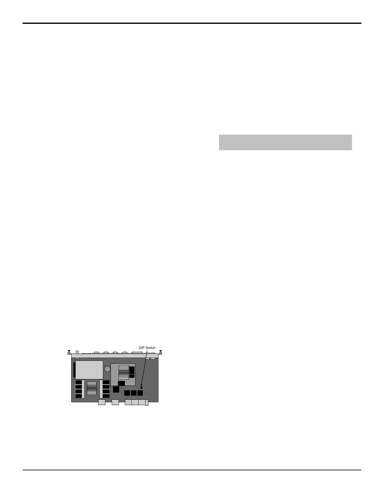
To Perform a DIP Switch Test
The DIP test allows you to verify the current settings of
the DIP Switch on the Frame CPU board (4810AR-002).
To conrm this test, you must remove the Frame CPU
board to verify the setting of the DIP Switch. Contact
Ross Video Technical Support before attempting to
change any DIP switch setting on the Frame CPU board.
Press HOME > More > Diagnostics > Frame
Diagnostics > DIP Test.
Figure 22: DIP Switch
The menu shows the number of DIP switches on the
Frame CPU board, what they do, and what position they
are currently in.
To Perform a Frame Tx/Rx Test
The frame Tx/Rx test allows you to test the various serial
communications ports on the frame. This helps to
diagnose communications problems with external devices
that you may be having on a particular serial
communications port on the frame.
1. Press HOME > More > Diagnostics > Frame
Diagnostics > Tx/Rx Test.
2. Use the Com Port knob to select the serial port on
the frame you want to test.
Tip: Press Loop to select whether the switcher performs
the test continuously (Yes, or only once (No).
3. Press Test.
To Perform a GPI Test
The GPI test allows you to test the functionality of each
GPI input and output on the switcher. A graphical
representation of each GPI indicates whether a particular
GPI is on or off.
1. Press HOME > More > Diagnostics > Frame
Diagnostics > GPI Test.
2. Use the Slot knob to select the board that you want
to perform the test on.
3. Press All On to turn all the GPIs on, All Off to turn
all GPIs off, and Prev and Next to run through the
GPIs one-by-one.
The current GPI is listed on the menu.
To Perform a Tally Test
The tally test allows you to test the standard parallel tally
system of the frame. A Tally Test Box is required to
ensure that the tally relays are operating properly.
1. Press HOME > More > Diagnostics > Frame
Diagnostics > Tally Test.
2. Use the Slot knob to select the board that you want
to perform the test on.
3. Press All On to turn all the tallies on, All Off to turn
all tallies off, and Prev and Next to run through the
tallies one-by-one.
The current tally is listed on the menu.
To Perform a Contact Closure Test
The contact closure test allows you to test the contact
closure system of the frame. A graphical representation
of each contact closure indicates whether a particular
contact closure is on or off.
1. Press HOME > More > Diagnostics > Frame
Diagnostics > Contact Closure Test.
98 • Frame Diagnostics — Acuity Setup Manual (v9.2)
 Loading...


