GPI Control
General Purpose Interface (GPI) is a high/low voltage
signalling protocol that allows the switcher to send simple
commands to an external device, or receive commands
from a device. Each pin on the GPI is set as either high
(+5 Volts), or low (0 Volts), and it is the switching
between high and low that sends commands to the
external device, or to the switcher.
The switcher has both xed and congurable GPIs. The
10 xed GPI inputs and 10 xed GPI outputs are located
on the Frame CPU board. The 24 GPIs on each Reference
with Tally board can be congured as either an input, or
an output.
GPI Trigger Types
There are four trigger types supported by the switcher.
These can be either output triggers, or input triggers.
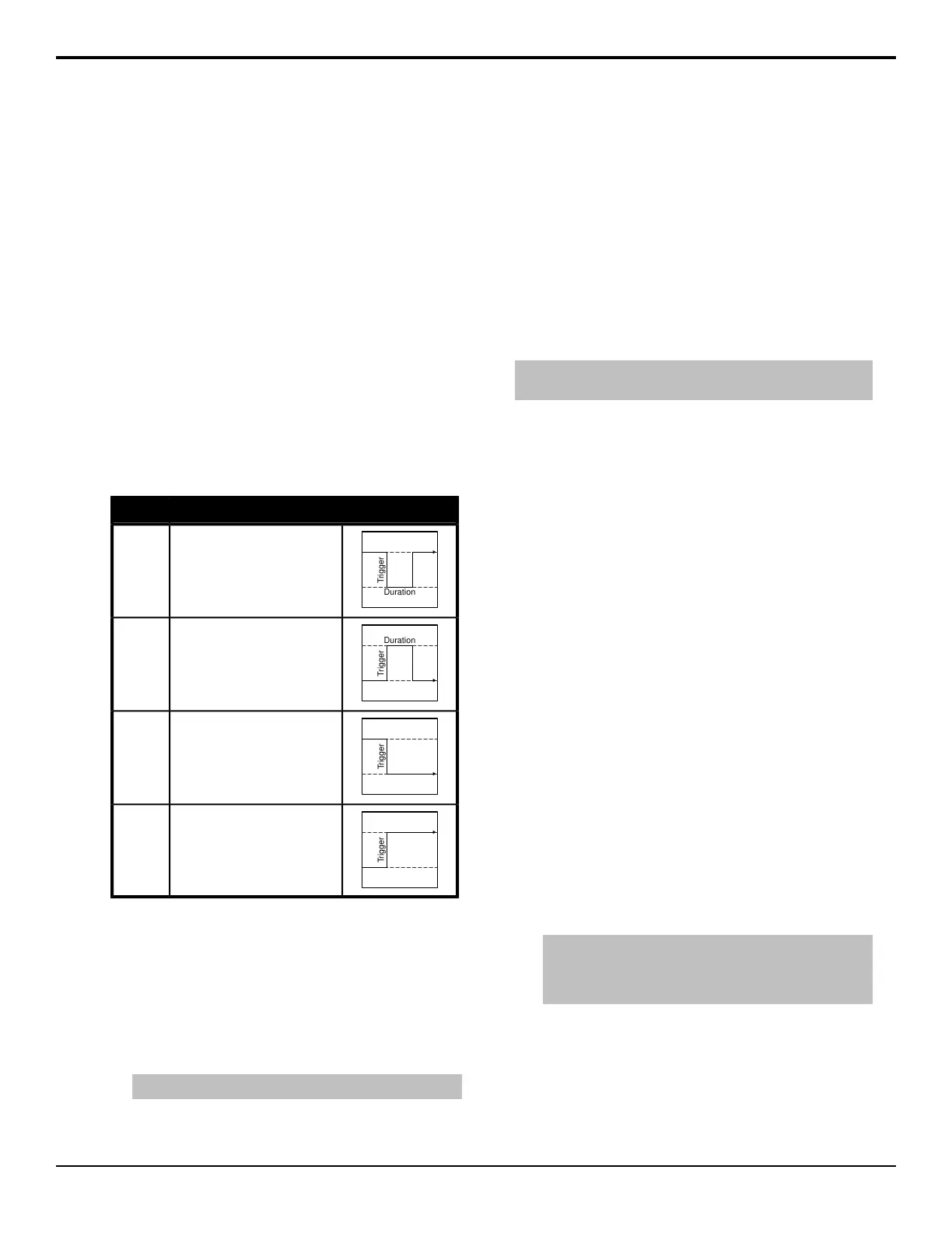
DescriptionTrigger
The output level is set high,
and momentarily goes low for
the trigger.
Pulse
Low
The output level is set low, and
momentarily goes high for the
trigger.
Pulse
High
The output level toggles from
the base high level to the low
level. The output signal
remains at this level until reset.
Level
Low
Trigger
<image audience="print" href="EffDiss.png" align="center" placement="break" scale="100"/>
The output toggles from the
base low level to the high level.
The output signal remains at
this level until reset.
Level
High
To View the Status of a GPI
1. Press HOME > Setup > Installation > GPI
Input/Output > More.
2. Press View GPI Inputs or View GPI Outputs to
view the status of the GPI inputs or outputs.
3. Use the middle knob to scroll the list.
Tip: Double-tap an item on the list to edit it.
To Name a GPI
1. Press HOME > Setup > Installation > GPI
Input/Output > Name GPI.
2. Use the bottom knob to select the GPI output you
want to name.
3. Enter the new name in the New Name eld.
4. Press Accept New Name.
5. Press HOME > Confirm.
To Set the Direction of a GPI
Note: Only the GPIs on the Reference with Tally board support
setting a direction.
1. Press HOME > Setup > Installation > GPI
Input/Output > GPI Direction.
2. Use the GPI knob to select the GPI that you want
to set as an input or output.
3. Use the Direction knob to set the GPI as an Input
or an Output.
4. Press HOME > Confirm.
GPI Inputs
GPI inputs can be used to trigger a number of events on
the switcher from a GPI I/O device. An example of a
commonly used GPI input is the small, hand-held, trigger
a weather forecaster uses to advance though the different
backgrounds in the weather forecast.
When the switcher receives a trigger on the selected GPI
input, it runs the events that have been assigned to the
GPI input.
To Set Up a GPI Input
1. Press HOME > Setup > Installation > GPI
Input/Output > Inputs.
2. Use the GPI Input knob to select the GPI input that
you want to assign an event to.
3. Use the Function knob to select the type of event
that you want to assign to the selected GPI input.
Tip: The Cut and Auto event start a transition in the
transition area of the selected ME. Use a memory recall to
set up the transition area with the keys and/or background
that you want transitioned before the GPI input occurs.
• Off — no event is triggered.
• Auto — an auto transition is performed on the
selected ME or Fade To Black module. Use the
Area knob to select where you want to transition
performed.
• Cut — a cut transition is performed on the
selected ME or Fade To Black module. Use the
Acuity Setup Manual (v9.2) — GPI Control • 53
 Loading...


