or text color, depending on whether you have
selected an invert font.
• Standard — use the standard mnemonics color.
• Green — use a green color.
• Red — use a red color.
• Blue — use a blue color.
• Yellow — use a yellow color.
• Orange — use an orange color.
• Purple — use a purple color.
• ME X Glow — use ME Glow color X.
• Aux Glow — use the aux glow color.
• CC Glow — use the CC glow color.
• User Color X — use User Color X.
• None — don't use a color for the mnemonic.
7. Press Accept New Name.
To Assign a Page to a Shot Box
Assigning pages to buttons allows you to switch between
pages by pressing the button on the Shot Box module,
just like switching between custom control banks on the
bus.
Note: If more than one Shot Box module is assigned to the
same panel row, both modules will mirror each other. You cannot
have two Shot Box modules operate independently if they are
assigned to the same panel row. The A1S Acuity Virtual Panel
is the exception where the second Shot Box is assigned to row
2 (the row of the first module +1).
1. Press HOME > Setup > Installation > More >
Custom Controls > Setup Shot Box Modules.
2. Use the Module Row knob to select the row that
the Shot Box or auxiliary control panel is assigned
to.
3. Use the Set Current Module Page knob to select
the shot box page that you want to assign to the
modules on the selected row.
4. Use the Set Link on Button knob to select the
button that you want to assign the selected page to
or select None.
Only buttons 1 through 14 are available on the
auxiliary control panel.
5. Press HOME > Confirm.
To Copy or Move a Page
1. Press HOME > Custom Controls > More >
Setup Shot Box Pages > Copy/Move Pages.
2. Use the Source knob to select the page you want
to copy or move.
3. Use the Destination knob to select the page that
you want to paste to source page to.
4. Press Copy or Move to copy or move the selected
source page to the destination page.
All the content of the destination page are replaced
with the contents of the source page. In the case of
a move, the source page is left empty after the move.
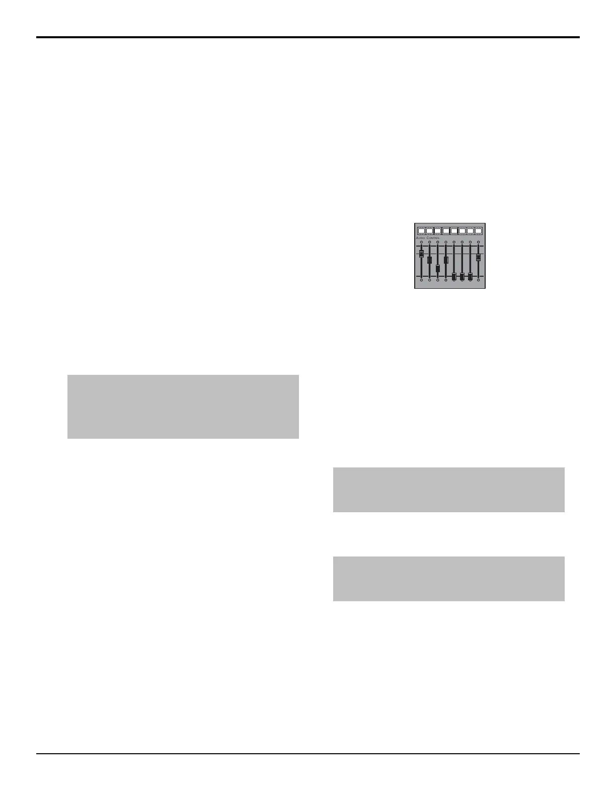
Audio Control Module
The Audio Control module allows you to map audio
channels, or groups, from an audio mixer to any of the
audio fader on the Audio Control module.
Figure 17: Audio Control Module
When an audio channel, or group, is assigned to a slider,
the source name for that audio channel is shown in the
mnemonic above the audio fader. Audio channels, or
groups, can be dynamically assigned to audio faders with
a custom control.
The color of the mnemonic above each audio fader
indicates the state of the audio channel, or group,
assigned to the fader
• Orange — Indicates that a channel assigned to that
fader is on-air.
• Yellow — Indicates that all channels assigned to that
fader are off-air.
Note: The switcher supports a maximum of four (4) Audio
Control modules connected to a control panel. Two can be
installed inside the control panel, and two outside the control
panel.
To Map an Audio Control Module to a Panel
Row
Note: The SideSlide and SideSlideNet are net set up in the
same way. Refer to the To Set Up Communication to a
SideBoxNet Module on page 74 section for information on setting
up communications with a SideSlideNet.
1. Press HOME > Setup > More > Panel Modules.
2. Press Yes.
3. Press a button on the module that you want to assign
to a row. This sets the Link/Node knob to that
module.
4. Press Panel Row & Crosspoint.
5. Use the Panel Row knob to select the panel row
that you want to assign the module to.
6. Press Audio Fader.
76 • Panel Modules — Acuity Setup Manual (v9.2)
 Loading...


